Flux Reference Manual

  • Welcome to Flux
  • Introduction
    • Installing the Software
    • The User Interface
    • Part Workflow
    • The Machine Database
  • Cut
    • Basic Workflows
      • Part Workflow
        • Load Part
        • Sketch Mode
        • Measure
        • Modifying Laser Part
        • Nesting
        • Sequence Navigator
        • NC Code Generation
      • Job workflow
        • Create Job
        • Set Laser Technology Table (LTT)
        • Nesting
        • Automatic Part Placement
        • Manual Part Placement
    • Advanced Topics
      • Geometry Import Options
      • Advanced Tooling Options
        • Editing Microjoints
        • TwinLine
        • FlyLine
        • Dimple Approach
        • Remainder Sheets
        • Pie-Slug Circular Holes
        • Avoid Retooling Pierces
        • Finishing Rules
        • Clone LTT
      • Advanced Nesting Features
        • Mirrored Parts
        • Find a Part in Nest Layout
        • Filler parts in Nest Layout
      • Advanced Tooling Optimization
        • Contour Quality
        • Optimizing Stability with Scrap Cutting
        • Optimizing Tilting Behaviour
        • Space Out Slice Cuts to Avoid Collision
        • Minimize Number of Different Layouts
        • Dynamic Level Setting
      • Advanced Menu Options
        • Context Sensitive Menus
        • Hierarchy of Settings
        • Multi-Selections
        • CSV Output
      • Manual Sheet Slicing Cuts
      • Text on Parts
    • Application Settings
      • Cut CAM
        • Layout
          • Nest Settings
          • Sheet
          • Sheet Handling
          • Skeleton Cuts
          • Work Support
        • Laser CAM
          • Sequence
      • Cut Outputs
      • Cut View
  • Bend
    • Basic Steps of Flux Bend
    • Basic Workflow
      • The Main Panel
      • The Workflow Panel
      • Batch processing
      • Modifying the Geometry
      • The Bend Navigator
      • Editing the Bend Solution
        • Editing a Bend
        • Changing the Bending Sequence
        • Editing a Tool Mount
        • Editing a Bend Setup
        • Editing the Back-Gauges
        • Angle Measurement
        • Using a Pre-Bend
        • Editing multiple mounts
        • Adding a Tooling station
      • Recomputing the Bend Solution
      • Generating Bend Outputs
      • Export Bend Report
    • Design of bend parts
      • Min Radius and Flange Length
      • Corner Design
      • Bending Tolerances
      • Selection of Tools
    • Advanced Workflow
      • Preparation of Bend Parts
        • Preparing a 2D drawing
        • Editing a Drawing
        • Add Bending Information as Text to DXF
        • Measuring and changing Outer Dimension
        • Preparing 3D models
        • Preparing an Assembly
        • Component Detection
        • Form Detection
      • Edit Tools
        • Changing Tool Map
        • Change Tool Segmentation
        • Editing Tool-mount Segments
        • Adding a Gap into the Tool
        • Use a Double-V Adapter
        • Tool Priority
        • Creating a Tool
      • Using Bend Deductions
      • Control Visibility
      • Comment Section in Bend Panel
      • Tools/Machine Tonnage Check
    • Settings
      • Application Settings
        • Bend CAM
          • Bend Outputs
          • Bend View
          • Bend Cell
      • Database Settings
        • Materials
        • Machines
        • Bend Tools
        • Bend Deductions
        • Bend grippers
        • Forms/Components
      • Bend Settings
      • Machine Defaults
  • Robotic Bending
    • Overview of Robotic Bending
    • Basic Steps of Robotic Bending
    • Workflow
      • Part Pickup
        • Pickup from a Pallet
        • Pickup from a Dispenser
      • Insertion Strategy
      • Bending Strategy
      • Regripping (RG) Stations
        • Re-Grip Stations
        • Methods of Regripping
        • Adding ReGrip
        • Modify ReGrip Position
        • Remove ReGripping
        • Regrip with a Jaw Gripper
        • Gripper Panel & Suction Panel
      • Extraction Strategy
      • Part Deposit
        • Adapt Part Deposit
        • Adding Parts & Stacks
          • Deposit Panel
          • Add Separator Sheets
          • Lock Part-Rest
          • Repeat Grid Field
          • Deposit Sequence
        • Deposit Pattern Types
      • Waypoints
        • Adapt WayPoints
        • Display Waypoints
        • Simulate Waypoints
        • Modify WayPoints
        • Properties of Waypoints
    • Advanced Topics
      • Cell Configuration
        • Track Setup
        • Gripper Inventory
        • BendCell settings
      • Gripper Configuration
        • Create/ Edit a Gripper
        • Import Gripper from DXF
    • Troubleshooting Bend Errors
      • Part Pickup Error
      • Collisions with Machine
      • Overtravel of Axis
      • Modifications of Waypoints
      • Collisions while Insertion and Extraction
  • Fold
    • Switching to Fold CAM
    • The Fold View
    • Editing Operations
      • Editing a Bend-Op
      • Editing a Side/Section
      • Changing the Sequence
      • Editing the Blank-holders
      • Editing the Gauging
      • Editing the Blades
      • Editing the Loading
      • Editing the Unloading
    • Tool Management
    • Fold CAM Summary
  • Generic Application Settings
    • Drawing
      • Layers
      • Dimensions
      • View
    • Environment
    • Import/Export
  • Flux Reports
    • Report Designer
    • Fields, Pictures and Tables
    • Bands (sub-reports)
    • Labels, Bitmaps and Shapes
  • Appendix
    • Supported 3D Formats
    • Separator Sheet DXF
Bend
/
Basic Workflow
/
Editing the Bend Solution
/
Editing multiple mounts

Editing multiple mounts

newitem202

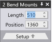
If you select multiple mounts by using Shift+Click on all of them, they can be edited together. Only settings and operations that are common to all the mounts are available for editing. Fields such as Length or Position are displayed for editing, only if they are the same for all the mounts. If you have multiple stations, it is useful to select all the punches or all the dies before doing a Change Tool operationIn this case, the choice of available replacement tools is more extensive (since there is no danger of different-height punches and dies causing a collision).

Dragging a bend-tool mount

The Position input can be used to set a precise position for a mount. Sometimes, it is easier to just drag a bend-mount to a new position. To do this:

  • Click on the bend mount to select it (select multiple mounts using Shift+Click)

  • Click and start dragging left or right to move the selected mount.

newitem203

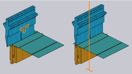
As shown in the image above, when you hover the mouse over a selected mount, the arrow-head is displayed indicating that you can drag the selected mount. When you are dragging the mount, snap indicators let you easily align the mount to other existing mounts.

If you pick up a mount near its left edge, then the left edges of all mounts are used for snapping. If you pick up a mount by the center, then the center-line is used for snapping, and so on.

Replace Tool

When you click on the Change Tool button, the Replace Tool window is displayed:

newitem204

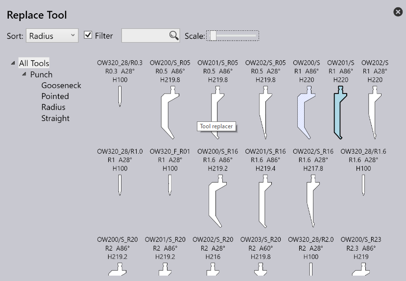
This window displays all the possible replacement tools.

  • Use the hierarchy on the left to narrow down the choices - for example, you could choose to display only Gooseneck tools, to make the selection easier.

  • Use the Sort selector on the top to sort the tools by name, height, radius or other sort criteria (the exact set of sort criteria depends on whether you are replacing a punch, die or adapter).

  • You can type in a tool name (or short-name) into the Search box to quickly narrow down the list. Typing in a partial tool name is fine too - using OW200 for example will match both OW200, OW200/S and OW200/K tools.

  • Use the Scale slider to adjust the sizes of the tool imagesThe tool that is currently used has a blue fill and a thick outlineThe light-blue cross-hatch indicates other tools that are used in this part.

  • Turn OFF the Filter checkbox to have an unrestricted view of all tools (regardless of whether they are suitable or not)In this view, the tools that are not suitable are grayed out, and moving the mouse over one of these tools indicates why it is not available for selection:

newitem205

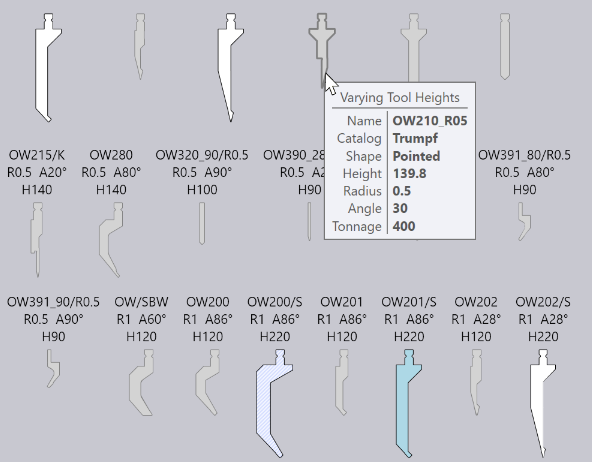
As you hover the mouse over the tool images, Flux Bend immediately re-computes the selected tool mounts using the newly selected tool, and you can see in real-time whether the tool you are considering will cause any collision problems or not (the corresponding bends in the bend-navigator will instantly light up in red if there is a collision). This real-time preview makes it very easy for you to experiment with various tool choices until you find one that works.

If you click on one of the tools, the choice is made and the new tool is applied to the part. If you press Escape instead, the preview choices you made are reverted back and the original tool is left unchanged.

Contents

  • Dragging a bend-tool mount
  • Replace Tool
Using a Pre-Bend Adding a Tooling station

      Copyright © 2023 by Metamation. All rights reserved.

    Compiled by Bento