Flux Reference Manual

  • Welcome to Flux
  • Introduction
    • Installing the Software
    • The User Interface
    • Part Workflow
    • The Machine Database
  • Cut
    • Basic Workflows
      • Part Workflow
        • Load Part
        • Sketch Mode
        • Measure
        • Modifying Laser Part
        • Nesting
        • Sequence Navigator
        • NC Code Generation
      • Job workflow
        • Create Job
        • Set Laser Technology Table (LTT)
        • Nesting
        • Automatic Part Placement
        • Manual Part Placement
    • Advanced Topics
      • Geometry Import Options
      • Advanced Tooling Options
        • Editing Microjoints
        • TwinLine
        • FlyLine
        • Dimple Approach
        • Remainder Sheets
        • Pie-Slug Circular Holes
        • Avoid Retooling Pierces
        • Finishing Rules
        • Clone LTT
      • Advanced Nesting Features
        • Mirrored Parts
        • Find a Part in Nest Layout
        • Filler parts in Nest Layout
      • Advanced Tooling Optimization
        • Contour Quality
        • Optimizing Stability with Scrap Cutting
        • Optimizing Tilting Behaviour
        • Space Out Slice Cuts to Avoid Collision
        • Minimize Number of Different Layouts
        • Dynamic Level Setting
      • Advanced Menu Options
        • Context Sensitive Menus
        • Hierarchy of Settings
        • Multi-Selections
        • CSV Output
      • Manual Sheet Slicing Cuts
      • Text on Parts
    • Application Settings
      • Cut CAM
        • Layout
          • Nest Settings
          • Sheet
          • Sheet Handling
          • Skeleton Cuts
          • Work Support
        • Laser CAM
          • Sequence
      • Cut Outputs
      • Cut View
  • Bend
    • Basic Steps of Flux Bend
    • Basic Workflow
      • The Main Panel
      • The Workflow Panel
      • Batch processing
      • Modifying the Geometry
      • The Bend Navigator
      • Editing the Bend Solution
        • Editing a Bend
        • Changing the Bending Sequence
        • Editing a Tool Mount
        • Editing a Bend Setup
        • Editing the Back-Gauges
        • Angle Measurement
        • Using a Pre-Bend
        • Editing multiple mounts
        • Adding a Tooling station
      • Recomputing the Bend Solution
      • Generating Bend Outputs
      • Export Bend Report
    • Design of bend parts
      • Min Radius and Flange Length
      • Corner Design
      • Bending Tolerances
      • Selection of Tools
    • Advanced Workflow
      • Preparation of Bend Parts
        • Preparing a 2D drawing
        • Editing a Drawing
        • Add Bending Information as Text to DXF
        • Measuring and changing Outer Dimension
        • Preparing 3D models
        • Preparing an Assembly
        • Component Detection
        • Form Detection
      • Edit Tools
        • Changing Tool Map
        • Change Tool Segmentation
        • Editing Tool-mount Segments
        • Adding a Gap into the Tool
        • Use a Double-V Adapter
        • Tool Priority
        • Creating a Tool
      • Using Bend Deductions
      • Control Visibility
      • Comment Section in Bend Panel
      • Tools/Machine Tonnage Check
    • Settings
      • Application Settings
        • Bend CAM
          • Bend Outputs
          • Bend View
          • Bend Cell
      • Database Settings
        • Materials
        • Machines
        • Bend Tools
        • Bend Deductions
        • Bend grippers
        • Forms/Components
      • Bend Settings
      • Machine Defaults
  • Robotic Bending
    • Overview of Robotic Bending
    • Basic Steps of Robotic Bending
    • Workflow
      • Part Pickup
        • Pickup from a Pallet
        • Pickup from a Dispenser
      • Insertion Strategy
      • Bending Strategy
      • Regripping (RG) Stations
        • Re-Grip Stations
        • Methods of Regripping
        • Adding ReGrip
        • Modify ReGrip Position
        • Remove ReGripping
        • Regrip with a Jaw Gripper
        • Gripper Panel & Suction Panel
      • Extraction Strategy
      • Part Deposit
        • Adapt Part Deposit
        • Adding Parts & Stacks
          • Deposit Panel
          • Add Separator Sheets
          • Lock Part-Rest
          • Repeat Grid Field
          • Deposit Sequence
        • Deposit Pattern Types
      • Waypoints
        • Adapt WayPoints
        • Display Waypoints
        • Simulate Waypoints
        • Modify WayPoints
        • Properties of Waypoints
    • Advanced Topics
      • Cell Configuration
        • Track Setup
        • Gripper Inventory
        • BendCell settings
      • Gripper Configuration
        • Create/ Edit a Gripper
        • Import Gripper from DXF
    • Troubleshooting Bend Errors
      • Part Pickup Error
      • Collisions with Machine
      • Overtravel of Axis
      • Modifications of Waypoints
      • Collisions while Insertion and Extraction
  • Fold
    • Switching to Fold CAM
    • The Fold View
    • Editing Operations
      • Editing a Bend-Op
      • Editing a Side/Section
      • Changing the Sequence
      • Editing the Blank-holders
      • Editing the Gauging
      • Editing the Blades
      • Editing the Loading
      • Editing the Unloading
    • Tool Management
    • Fold CAM Summary
  • Generic Application Settings
    • Drawing
      • Layers
      • Dimensions
      • View
    • Environment
    • Import/Export
  • Flux Reports
    • Report Designer
    • Fields, Pictures and Tables
    • Bands (sub-reports)
    • Labels, Bitmaps and Shapes
  • Appendix
    • Supported 3D Formats
    • Separator Sheet DXF
Cut
/
Basic Workflows
/
Part Workflow
/
Modifying Laser Part

Modifying Laser Part

After creating part in sketch mode, use the workflow to select laser tech or use shortcut key L. The part will be tooled. Select the part to preview of the approach path is shown while moving it. If the approach is being moved to a tight corner, user can see that the approach is being shortened. Further, if the traverse-lines view is on, one can also see that the routing will be dynamically updated as the user is moving the approach.

Example: If the user is moving approach point to the opposite side of the hole, a head-down reposition to the next cut could change to a head-up reposition.
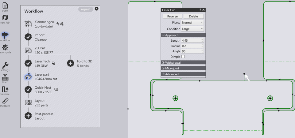
cutmod

Pierce
Allows you to choose the pierce type. Possible pierce types vary from machine to machine. Depending on the selection of pierce type, the marker drawn to indicate pierce point in the editor will change.
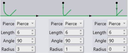
Length & Radius
The following illustrations will clarify its meaning in different circumstances. Note that with fixed length, increasing the radius would shorten the straight segment of approach geometry.
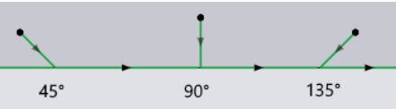
cutpierce

Angle
Whether for approach or for escape, a greater angle would imply that the laser head must make a sharper turn.

modangle

Contour

Selecting all tooling on the current polyline and provides a special panel using which actions on the contour (inner or outer) can be performed as a whole.

lasercontour

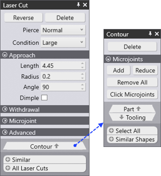
For example, microjoints on the contour or chute conditions could be assigned from the 'Contour' panel.

Selection buttons at the bottom allows you to select similar or all laser cuts. Cuts are considered similar if they start and end at congruent points on identical polylines.

Corner Treatment

cornertreat
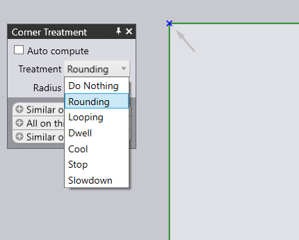
Corner treatment option is available only after tooling a Laser Part.

Click on in the CutCAM mode on a corner and select Corner Treatment.

Once a part is imported and clean up of the part is complete, the part is ready to be tooled. Once tooled, modification of the corner treatment of the part can be done by the user. Selecting a corner of the part will display the Corner Treatment dialogue.

Auto Compute - This option automatically computes the best suited treatment for the selected corner.

Treatment - This displays a drop-down menu to which corner treatment is desired.

Treatment Explanation Example

Do Nothing

No corner processing performed.

donothing

Rounding

Rounds off at the corners.

round

Looping

Loops at the corners.

loop

Dwell

Dwells at the corners.

dwell

Cool

Cools down the laser at the corners.

cool

Stop

Stops at the corner.

stopcorner

Slowdown

Slows down the laser at the corners.

slowdown

Radius - This will sets a radius for the selected corner.

Click and hold Ctrl key and scroll the mouse wheel for coarse increment.
Click and hold Shift key and scroll the mouse wheel for fine increment.

Similar on this contour - This option will select all similar corners on the selected contour.

All on this contour - This option will select all corners on the selected contour.

Similar on all contours - This option will select all similar corners on all contours.

Contents

  • Corner Treatment
Measure Nesting

      Copyright © 2023 by Metamation. All rights reserved.

    Compiled by Bento