Insertion Strategy
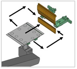
With the Insertion option under Robot strategy settings, BendMaster moves the part from the front, right or left to the bending position. The part is first positioned above the lower tool and then moved backwards (in X direction) to the backgauge fingers.
| A collision-free insertion is only possible, if the backgauge is positioned after the part has been moved to its programmed position. |
Corresponding adjustments can be made for the selected bend depending on the geometry of the part.
To navigate to strategy panel:
-
Double click on a bend number to open the Bend Panel.
-
Click Robot Strategy link to access the Strategy panel.
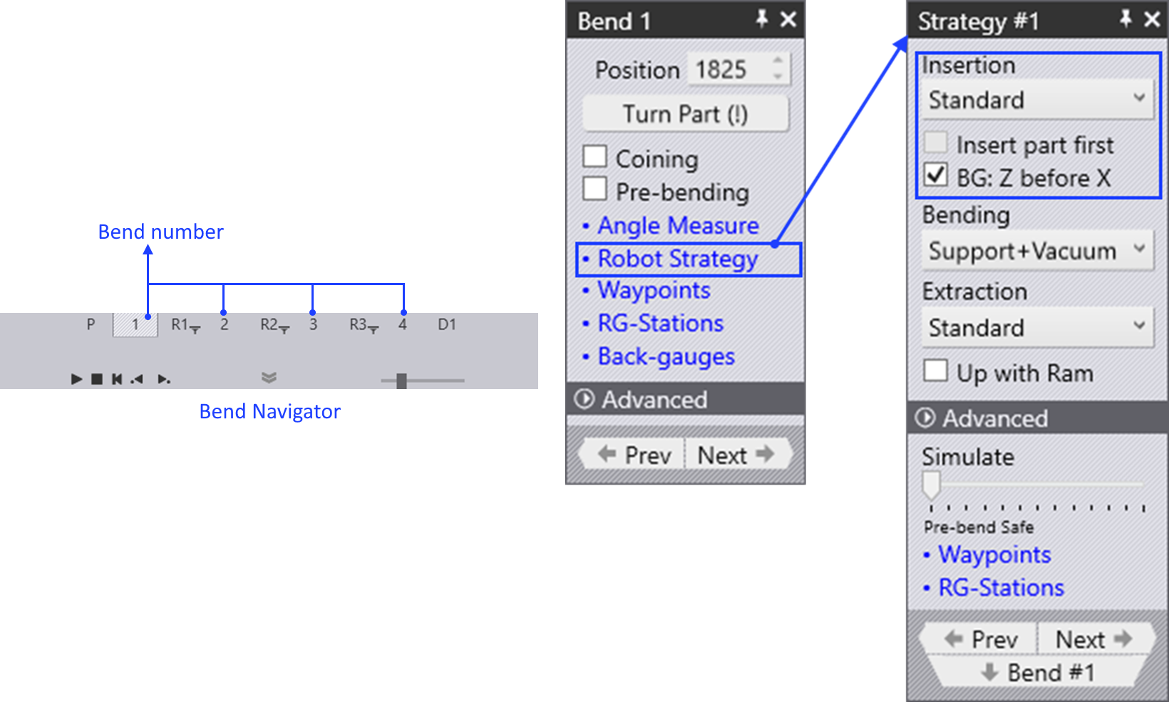
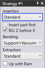
To use the insertion option, choose Insertion type from the Strategy panel. The three types of insertion are:
-
Standard
-
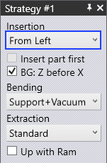
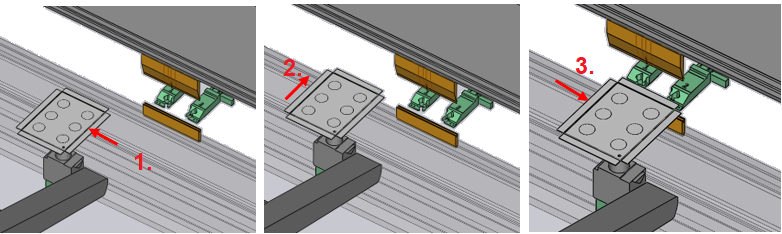
From Left
-
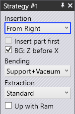
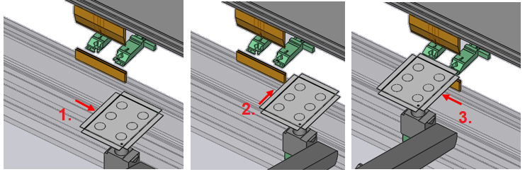
From Right
-
From the Insertion types, we can insert the part from the left or the right of the punch (sliding the part in between the punch and die) and use the standard insertion type. This can be useful if the part has some contour that might collide with the punch as the ram is closing.
Standard Position
In the Standard position, the part is inserted in between the punch and die from the front.
From Left
In the From Left position, the part is inserted from the left side of the punch and die .
From Right
In the From Right position, the part is inserted from the right side of the punch and die .
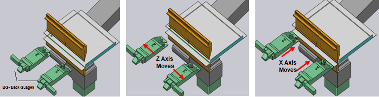
BG: Z before X
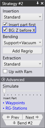
The BG: Z before X strategy is used to control how the back-gauge moves from the previous bending operation to this one. It is useful in the cases where the gauging position for the existing bend is closer to the die than the previous bend.
If this is turned ON, the back-gauges move first in the Z direction to get to the target Z1 and Z2 positions, and then move forward in X to the engagement position. This reduces the possibility of collisions with the part during the gauge movement.
The simulation gets updated when you change this setting, so you can visually see the gauge movement path. Flux RoboBend will usually figure out if this Z before X strategy is useful, and will turn on this setting automatically. You can use this check box to override the default selection.
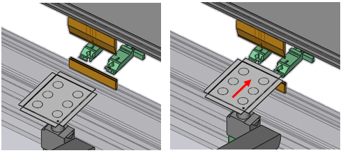
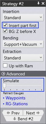
Insert Part First
Normally, the back-gauge moves from the previous bend position to the next gauging position as soon as the previous bend is completed and the part is extracted out.
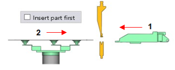
With the Insert first strategy, this movement is delayed. The part is first inserted and rested on the die. Then, the gauges are moved into position. This can be useful in situations where there are some downward facing flanges in the part that might collide with the gauges if they were already in position during the part-insertion. This simulation is updated when you change this setting, so you can see the gauge movement delayed until after part insertion is complete.
The Simulate slider can be used to quickly simulate just the insertion phases of this bend so you can quickly review the changes you are making.
1 Back gauge moves in first
2 Part moves in after
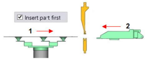
1 Part moves in first
2 Back gauge moves in after