Flux Reference Manual

  • Welcome to Flux
  • Introduction
    • Installing the Software
    • The User Interface
    • Part Workflow
    • The Machine Database
  • Cut
    • Basic Workflows
      • Part Workflow
        • Load Part
        • Sketch Mode
        • Measure
        • Modifying Laser Part
        • Nesting
        • Sequence Navigator
        • NC Code Generation
      • Job workflow
        • Create Job
        • Set Laser Technology Table (LTT)
        • Nesting
        • Automatic Part Placement
        • Manual Part Placement
    • Advanced Topics
      • Geometry Import Options
      • Advanced Tooling Options
        • Editing Microjoints
        • TwinLine
        • FlyLine
        • Dimple Approach
        • Remainder Sheets
        • Pie-Slug Circular Holes
        • Avoid Retooling Pierces
        • Finishing Rules
        • Clone LTT
      • Advanced Nesting Features
        • Mirrored Parts
        • Find a Part in Nest Layout
        • Filler parts in Nest Layout
      • Advanced Tooling Optimization
        • Contour Quality
        • Optimizing Stability with Scrap Cutting
        • Optimizing Tilting Behaviour
        • Space Out Slice Cuts to Avoid Collision
        • Minimize Number of Different Layouts
        • Dynamic Level Setting
      • Advanced Menu Options
        • Context Sensitive Menus
        • Hierarchy of Settings
        • Multi-Selections
        • CSV Output
      • Manual Sheet Slicing Cuts
      • Text on Parts
    • Application Settings
      • Cut CAM
        • Layout
          • Nest Settings
          • Sheet
          • Sheet Handling
          • Skeleton Cuts
          • Work Support
        • Laser CAM
          • Sequence
      • Cut Outputs
      • Cut View
  • Bend
    • Basic Steps of Flux Bend
    • Basic Workflow
      • The Main Panel
      • The Workflow Panel
      • Batch processing
      • Modifying the Geometry
      • The Bend Navigator
      • Editing the Bend Solution
        • Editing a Bend
        • Changing the Bending Sequence
        • Editing a Tool Mount
        • Editing a Bend Setup
        • Editing the Back-Gauges
        • Angle Measurement
        • Using a Pre-Bend
        • Editing multiple mounts
        • Adding a Tooling station
      • Recomputing the Bend Solution
      • Generating Bend Outputs
      • Export Bend Report
    • Design of bend parts
      • Min Radius and Flange Length
      • Corner Design
      • Bending Tolerances
      • Selection of Tools
    • Advanced Workflow
      • Preparation of Bend Parts
        • Preparing a 2D drawing
        • Editing a Drawing
        • Add Bending Information as Text to DXF
        • Measuring and changing Outer Dimension
        • Preparing 3D models
        • Preparing an Assembly
        • Component Detection
        • Form Detection
      • Edit Tools
        • Changing Tool Map
        • Change Tool Segmentation
        • Editing Tool-mount Segments
        • Adding a Gap into the Tool
        • Use a Double-V Adapter
        • Tool Priority
        • Creating a Tool
      • Using Bend Deductions
      • Control Visibility
      • Comment Section in Bend Panel
      • Tools/Machine Tonnage Check
    • Settings
      • Application Settings
        • Bend CAM
          • Bend Outputs
          • Bend View
          • Bend Cell
      • Database Settings
        • Materials
        • Machines
        • Bend Tools
        • Bend Deductions
        • Bend grippers
        • Forms/Components
      • Bend Settings
      • Machine Defaults
  • Robotic Bending
    • Overview of Robotic Bending
    • Basic Steps of Robotic Bending
    • Workflow
      • Part Pickup
        • Pickup from a Pallet
        • Pickup from a Dispenser
      • Insertion Strategy
      • Bending Strategy
      • Regripping (RG) Stations
        • Re-Grip Stations
        • Methods of Regripping
        • Adding ReGrip
        • Modify ReGrip Position
        • Remove ReGripping
        • Regrip with a Jaw Gripper
        • Gripper Panel & Suction Panel
      • Extraction Strategy
      • Part Deposit
        • Adapt Part Deposit
        • Adding Parts & Stacks
          • Deposit Panel
          • Add Separator Sheets
          • Lock Part-Rest
          • Repeat Grid Field
          • Deposit Sequence
        • Deposit Pattern Types
      • Waypoints
        • Adapt WayPoints
        • Display Waypoints
        • Simulate Waypoints
        • Modify WayPoints
        • Properties of Waypoints
    • Advanced Topics
      • Cell Configuration
        • Track Setup
        • Gripper Inventory
        • BendCell settings
      • Gripper Configuration
        • Create/ Edit a Gripper
        • Import Gripper from DXF
    • Troubleshooting Bend Errors
      • Part Pickup Error
      • Collisions with Machine
      • Overtravel of Axis
      • Modifications of Waypoints
      • Collisions while Insertion and Extraction
  • Fold
    • Switching to Fold CAM
    • The Fold View
    • Editing Operations
      • Editing a Bend-Op
      • Editing a Side/Section
      • Changing the Sequence
      • Editing the Blank-holders
      • Editing the Gauging
      • Editing the Blades
      • Editing the Loading
      • Editing the Unloading
    • Tool Management
    • Fold CAM Summary
  • Generic Application Settings
    • Drawing
      • Layers
      • Dimensions
      • View
    • Environment
    • Import/Export
  • Flux Reports
    • Report Designer
    • Fields, Pictures and Tables
    • Bands (sub-reports)
    • Labels, Bitmaps and Shapes
  • Appendix
    • Supported 3D Formats
    • Separator Sheet DXF
Cut
/
Advanced Topics
/
Advanced Tooling Options
/
TwinLine

TwinLine

TwinLine is a method wherein the tool width is equal to the distance between the contour lines of two adjacent sections on the sheet during nesting. Thus, just one cut is used in the processing of these two contours.

TwinLine leads to significant savings in terms of machine time and material usage.

To ensure the stability of the twinlined parts on the slat pins and the ability to automatically add microjoints to twinline groups, Flux comes with multiple options to create optimal twinline groups.

Slight marks of TwinLine could be seen on the edges.

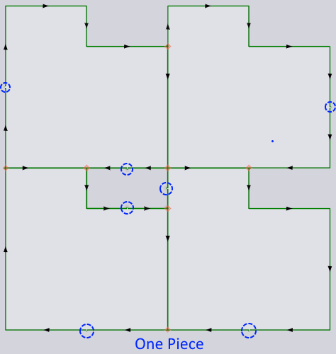
  • One piece: In this strategy, the software will add microjoints such that the whole block, including any islands, remains attached to the sheet as a single piece.

ne27
ne26
  • One free piece: Creating a twinline block tooling that holds up as a single piece not bound to the sheet skeleton. That is, there are no microjoints on the outer contour. Only on the islands and twinline edges.

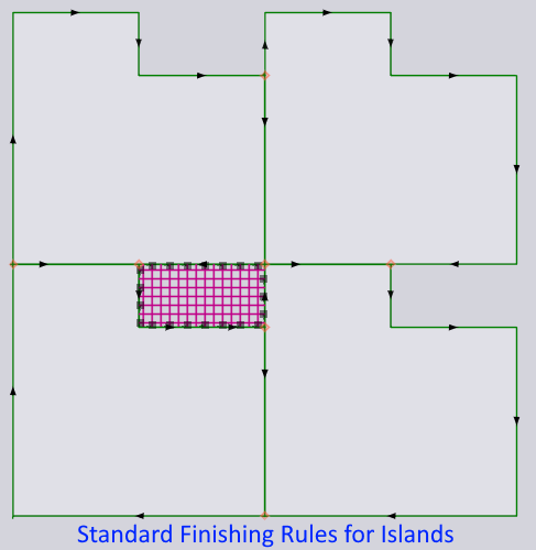
  • Standard finishing rules: Standard finishing rules are applied to islands. Tipping and stability analysis will be done for islands, and if the finishing rules prescribe microjoints, microjoints will be added, and if they prescribe scrap-tooling, scrap-tooling will be applied (and the entire island will be broken down).

Auto Selection between Safety and Easy Strategy

ne18

It is necessary for the software to support both the safety and easy strategy of twinline tooling. But Flux goes a step further and can analyze and automatically choose the right strategy for any given twinline group.

There are three strategies:

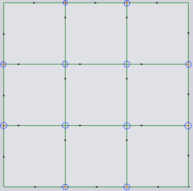
  1. TIO (TwinLine-Island-Outer) strategy: In this strategy, the software will create three different kinds of tooling paths from a twinline block.

    1. TwinLine: These are the twinline paths between overlapping edges of the adjacent parts. These are always open paths. Once the software detects these paths, they are cut first, before any other path.

    2. Island: These are sheet skeleton islands formed between parts of the block. These islands are cut next. Islands are always closed contours. Cutting an island always begins at a node that is already touched by a twinline path.

    3. Outer: There will always be one outer contour for a twinline block. This is always cut at the end. The software will approach this outer contour from the left-bottom or left-top, depending on the prescribed cutting direction (clockwise or anticlockwise) for outer contours in settings.

image
  1. Partwise-safe strategy: This strategy is similar (probably not identical) to the safety strategy of Trutops/Boost. In this strategy, cutting progresses to the next part only after the current part is cut completely free. At junction nodes where adjacent parts touch, preparatory cuts are made. The purpose of these preparatory cuts is to avoid the laser head coming close to a part that is already cut (and possibly tilting).

image

The software, when on islands, instead of just doing a precut, completely cuts the island free (as shown in the below image). If this is not done, when processing the last part, it is possible that the entire block is cut free before some inner islands are cut free.

image
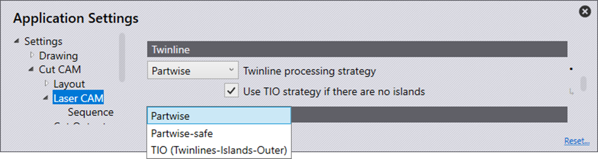
  1. Partwise strategy: This strategy is similar to the partwise-safe strategy, but there are no preparatory cuts. At junction nodes, cutting for the next part will resume 1.25 mm distance into the twinline path. That is, cutting will resume a little distance away from the junction node, again cutting a small portion of the cut path. This seems impossible for situations where parts could tilt, hence, it is recommended only for thick sheets where parts will not tilt. The user can choose the preferred strategy from the laser settings as shown in the screenshot below. The tooltip on the strategy explains the strategy and its applicability.

Nanojoints vs Microjoints in a TwinLine Situation

On twinlined edges, only nanojoints (or piercing on contour) are possible. On the edges of an island or outer boundary, all types of joints (hard, soft, or nano) are possible. When applying the One Piece strategy, Flux will try to minimize the number of joints on the twinlined edge with the assumption that hard/soft joints (with an approach path) are preferred over nanojoints (where piercing is done on the contour). Nanojoints are shown with tiny yellow dots.

image
image
If the preferred joint type is set to nano in settings, then some joints on islands/outer will also eventually be nanojoint.

Manual microjoints for TwinLine groups

Apart from adding these microjoints automatically, the software allows for manually adding/removing microjoints anywhere on a twinline tool by just clicking.

Slowing down at TwinLine junctions

When cutting with TwinLine easy strategy, it is better if the cutting speed is reduced when crossing over already-cut edges.

image

Contents

  • Auto Selection between Safety and Easy Strategy
  • Nanojoints vs Microjoints in a TwinLine Situation
  • Manual microjoints for TwinLine groups
  • Slowing down at TwinLine junctions
Editing Microjoints FlyLine

      Copyright © 2023 by Metamation. All rights reserved.

    Compiled by Bento