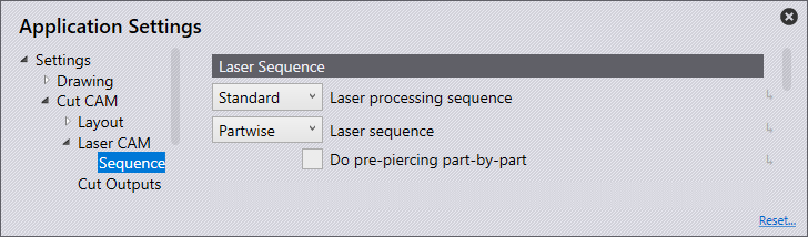
Flux Reference Manual

  • Welcome to Flux
  • Introduction
    • Installing the Software
    • The User Interface
    • Part Workflow
    • The Machine Database
  • Cut
    • Basic Workflows
      • Part Workflow
        • Load Part
        • Sketch Mode
        • Measure
        • Modifying Laser Part
        • Nesting
        • Sequence Navigator
        • NC Code Generation
      • Job workflow
        • Create Job
        • Set Laser Technology Table (LTT)
        • Nesting
        • Automatic Part Placement
        • Manual Part Placement
    • Advanced Topics
      • Geometry Import Options
      • Advanced Tooling Options
        • Editing Microjoints
        • TwinLine
        • FlyLine
        • Dimple Approach
        • Remainder Sheets
        • Pie-Slug Circular Holes
        • Avoid Retooling Pierces
        • Finishing Rules
        • Clone LTT
      • Advanced Nesting Features
        • Mirrored Parts
        • Find a Part in Nest Layout
        • Filler parts in Nest Layout
      • Advanced Tooling Optimization
        • Contour Quality
        • Optimizing Stability with Scrap Cutting
        • Optimizing Tilting Behaviour
        • Space Out Slice Cuts to Avoid Collision
        • Minimize Number of Different Layouts
        • Dynamic Level Setting
      • Advanced Menu Options
        • Context Sensitive Menus
        • Hierarchy of Settings
        • Multi-Selections
        • CSV Output
      • Manual Sheet Slicing Cuts
      • Text on Parts
    • Application Settings
      • Cut CAM
        • Layout
          • Nest Settings
          • Sheet
          • Sheet Handling
          • Skeleton Cuts
          • Work Support
        • Laser CAM
          • Sequence
      • Cut Outputs
      • Cut View
  • Bend
    • Basic Steps of Flux Bend
    • Basic Workflow
      • The Main Panel
      • The Workflow Panel
      • Batch processing
      • Modifying the Geometry
      • The Bend Navigator
      • Editing the Bend Solution
        • Editing a Bend
        • Changing the Bending Sequence
        • Editing a Tool Mount
        • Editing a Bend Setup
        • Editing the Back-Gauges
        • Angle Measurement
        • Using a Pre-Bend
        • Editing multiple mounts
        • Adding a Tooling station
      • Recomputing the Bend Solution
      • Generating Bend Outputs
      • Export Bend Report
    • Design of bend parts
      • Min Radius and Flange Length
      • Corner Design
      • Bending Tolerances
      • Selection of Tools
    • Advanced Workflow
      • Preparation of Bend Parts
        • Preparing a 2D drawing
        • Editing a Drawing
        • Add Bending Information as Text to DXF
        • Measuring and changing Outer Dimension
        • Preparing 3D models
        • Preparing an Assembly
        • Component Detection
        • Form Detection
      • Edit Tools
        • Changing Tool Map
        • Change Tool Segmentation
        • Editing Tool-mount Segments
        • Adding a Gap into the Tool
        • Use a Double-V Adapter
        • Tool Priority
        • Creating a Tool
      • Using Bend Deductions
      • Control Visibility
      • Comment Section in Bend Panel
      • Tools/Machine Tonnage Check
    • Settings
      • Application Settings
        • Bend CAM
          • Bend Outputs
          • Bend View
          • Bend Cell
      • Database Settings
        • Materials
        • Machines
        • Bend Tools
        • Bend Deductions
        • Bend grippers
        • Forms/Components
      • Bend Settings
      • Machine Defaults
  • Robotic Bending
    • Overview of Robotic Bending
    • Basic Steps of Robotic Bending
    • Workflow
      • Part Pickup
        • Pickup from a Pallet
        • Pickup from a Dispenser
      • Insertion Strategy
      • Bending Strategy
      • Regripping (RG) Stations
        • Re-Grip Stations
        • Methods of Regripping
        • Adding ReGrip
        • Modify ReGrip Position
        • Remove ReGripping
        • Regrip with a Jaw Gripper
        • Gripper Panel & Suction Panel
      • Extraction Strategy
      • Part Deposit
        • Adapt Part Deposit
        • Adding Parts & Stacks
          • Deposit Panel
          • Add Separator Sheets
          • Lock Part-Rest
          • Repeat Grid Field
          • Deposit Sequence
        • Deposit Pattern Types
      • Waypoints
        • Adapt WayPoints
        • Display Waypoints
        • Simulate Waypoints
        • Modify WayPoints
        • Properties of Waypoints
    • Advanced Topics
      • Cell Configuration
        • Track Setup
        • Gripper Inventory
        • BendCell settings
      • Gripper Configuration
        • Create/ Edit a Gripper
        • Import Gripper from DXF
    • Troubleshooting Bend Errors
      • Part Pickup Error
      • Collisions with Machine
      • Overtravel of Axis
      • Modifications of Waypoints
      • Collisions while Insertion and Extraction
  • Fold
    • Switching to Fold CAM
    • The Fold View
    • Editing Operations
      • Editing a Bend-Op
      • Editing a Side/Section
      • Changing the Sequence
      • Editing the Blank-holders
      • Editing the Gauging
      • Editing the Blades
      • Editing the Loading
      • Editing the Unloading
    • Tool Management
    • Fold CAM Summary
  • Generic Application Settings
    • Drawing
      • Layers
      • Dimensions
      • View
    • Environment
    • Import/Export
  • Flux Reports
    • Report Designer
    • Fields, Pictures and Tables
    • Bands (sub-reports)
    • Labels, Bitmaps and Shapes
  • Appendix
    • Supported 3D Formats
    • Separator Sheet DXF
Cut
/
Application Settings
/
Cut CAM
/
Laser CAM
/
Sequence

Sequence

lasersequence

Laser Sequence

Laser Processing Sequence

Use this to define the laser processing sequence, this is useful if you have any piercing or marking that needs to be processed first.

Standard - No specific order is enforced between marking and cutting.

Mark Cut - Does all marking first and then cutting.

Pierce Cut - Splits all laser tooling into piercing operation and then cutting operation. All pierces are done first followed by cut/mark operations.

Mark Pierce Cut - Like above but all markings are finished first.

Pierce Mark Cut - Like the third option but between cut & mark, marking is done first.

Laser Sequence

This drop-down gives options to choose the laser sequence.

Partwise - If this choice is selected, sequencing is done part wise. Once operations on a part starts, it will proceed to another part only after all operations on that part are finished. It is not necessary that the sequence within each part is same across all its instances on the layout. Depending on where the machine head is coming from and where it needs to go next, the order within a part could vary across instances of the same part.

Partwise Native - If this option is selected, sequencing is done partwise. Once operations on a part start, it will proceed to another part only after all operations on that part are finished. The sequence within a part and all its instances will be same as the part native tooling.

Inner First - All tooling on inner contours are sequenced first followed by the outer contours.

Sort by contour size - All tooling on inner contours is processed before outer contours and will be sorted based on contour size.

Do pre-pierce part-by-part - Pierce operations will be done partwise. Once all the piercing is done on a part, it will finish the cut before proceeding to the next part.

Route Traverse

routetraverse

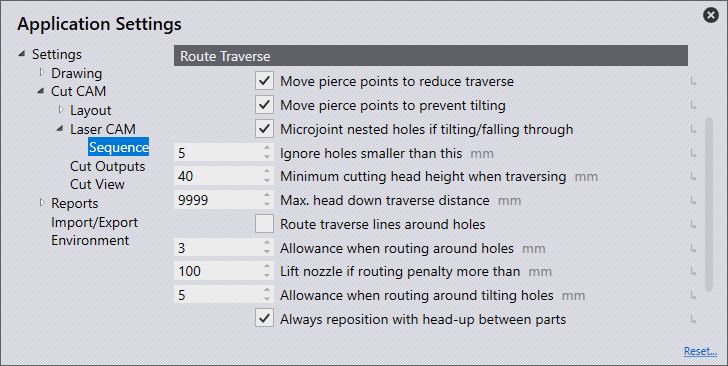
Move pierce points to reduce travel - This checkbox is to choose a different approach point location to reduce traverse distance.

Move pierce points to prevent tilting - This checkbox is to choose a different approach point location to avoid tipping of the cut-outs.

Microjoint nested holes if tilting/falling through - This checkbox is to microjoint a contour with parts nested inside of them only if the contour is evaluated as a fall through or being tilted.

Ignore holes smaller than this - Holes smaller than the given value are considered not big enough for the height sensor to dive the machine head into it and hence ignored.

Minimum cutting head height when traversing - Minimum head distance from the sheet when doing head-up traversal.

Max. head down traverse distance - The software automatically calculates a head down traverse limit based on nozzle distance from sheet. The lower of the calculated value and the value entered here will be used.

Route traverse lines around holes - Turn on to route the laser head around cut-outs, if possible, instead of lifting head up.

Allowance when routing around holes - When routing lines to avoid cut-outs, this distance will be maintained from the traverse path to the edge of a cut. If this value is too high to route traverse lines around the cut-outs, then those traverse lines will be processed with the machine head being raised.

Lift nozzle if routing penalty more than - This option is used to define if the nozzle should be lifted if the routing penalty is more than this value.

Allowance when routing around tilting holes - This option is to define the routing allowance around tilting holes.

Always reposition with head-up between holes - This option should be checked if subprograms should be safe for post-production.

Option - Laser heads

This section is applicable when relevant option is selected.
laserheads

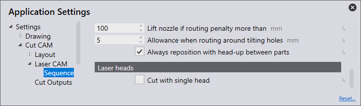
Cut with single head - This option is for dual head lasers to enable this to cut with a single laser head.

Contents

  • Laser Sequence
  • Laser Processing Sequence
  • Laser Sequence
  • Route Traverse
  • Option - Laser heads
Laser CAM Cut Outputs

      Copyright © 2023 by Metamation. All rights reserved.

    Compiled by Bento