Extraction Strategy
The extraction strategy defines the movement of the part after the bending process. Depending on the part geometry, different types of extraction strategies are available. In Flux RoboBend, a suitable solution is automatically offered, which can be changed if necessary. Below mentioned menus are used for adjusting the extraction strategy.
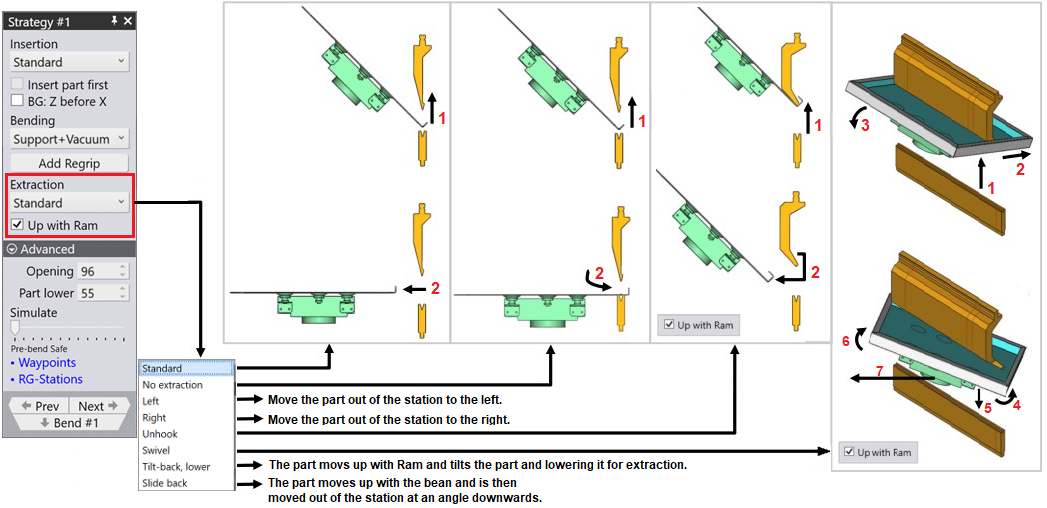
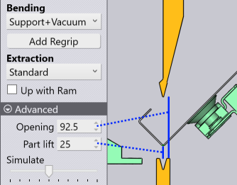
Standard Extraction
This is the most common extraction method. The part is lifted up and then extracted in X direction.
-
Opening: The beam opening.
-
Part lift: The part is lifted up from the bending position by this amount, before being extracted back.
Standard Extraction + Up with Ram
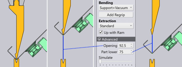
The Up with Ram checkbox is available for many of the extraction methods. For some of the extraction methods this is automatically assumed, and cannot be switched OFF. If this is set, then the part moves up along with the ram. So the Part lift setting is not required (it is similar to the beam opening).
Part lower: After traveling up with the ram, the part is then lowered down by this amount before being extracted back.
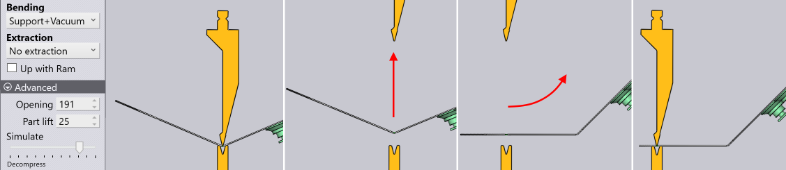
No Extraction
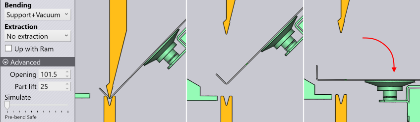
The No extraction strategy means that the part is not actually extracted out of the beam. Instead, the part directly proceeds to the next bend with just a pitch rotation to align it for bending. It can be used only when the two bends are adjacent bends on the same side of the part (no part turn required).
| This strategy can also be combined with the Up with Ram setting. |
Below is another example of the No extraction strategy. In this example, the part is moving backward between bend 1 and bend 2.
Left, Right Extractions
The Left and Right extraction strategies extract the part by first moving it sideways until the part clears the punch/die station. Then the part is extracted out in the X direction. The image below shows examples of both.
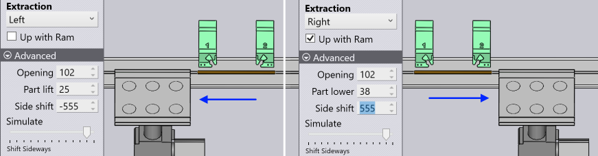
Side shift: This parameter controls the movement of the part in the Z direction before it is extracted out.
| The Left and Right extraction methods can be combined with the Up with Ram switch, as shown by the image above right. Here, the Right extraction method also uses Up with Ram - you can see that the Part lower parameter is introduced to control how much the part is lowered, after traveling up with the beam and before the sideways extraction. |
Unhook Extraction
The Unhook extraction strategy is used to unhook a flange from the recess of a gooseneck punch. The part is lifted up with the beam, then it slides forward following the angle of the punch. Then it is lowered and extracted out.
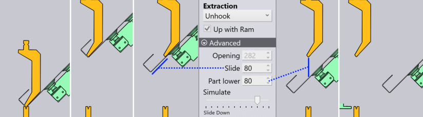
Slide: This is the distance the part is slid forward and down, following the angle of the punch.
Part lower: The distance the part is lowered after the forward slide.
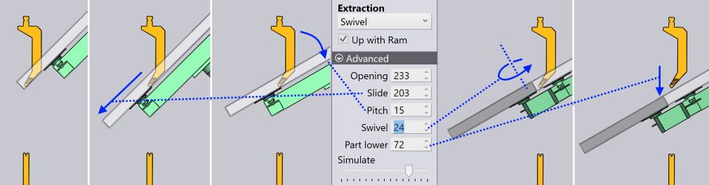
Swivel Extraction
The Swivel strategy is used to extricate a part where the side flanges are tucked into the shoulder recess of a punch. The extraction requires several stages as shown below, and is controlled using multiple parameters:
Slide: The distance the part is slid forward and down, following the angle of the punch.
Pitch: The part is tilted back (pitched) with the center of rotation close to the tip of the punch, until it is lying a bit more flat, in preparation for the next swivel step.
Swivel: The part is rotated about the wrist axis to release the punch tips form the overhanging flanges.
Part lower: The rotated part is lowered to clear the punch (in the next step, it is retracted back).
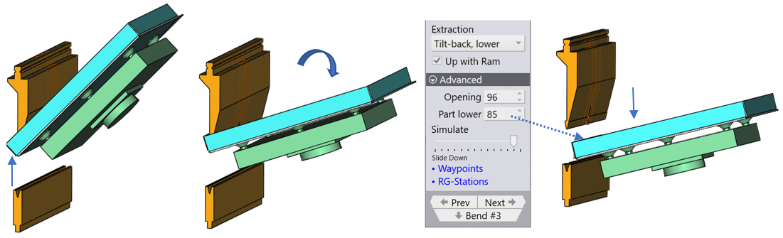
Tilt-Back Lower Extraction
The Tilt-Back Lower strategy is used to extracts a part with Up with Ram option enabled and Lower the part make it free from the Ram and the Die to avoid collision.
Opening: The beam opening to make enough space for the part to lower down
Part lower: The rotated part is lowered to clear the punch (in the next step, it is retracted back.
Slide Back
This extraction pattern is useful in extracting parts with tall flanges that are too tall to be removed out straight even with the beam at full opening. The part goes up with the beam, then moves down slightly and is extracted by a diagonal movement (similar to the unhook extraction, but moving backwards or towards the operator, instead of into the machine).
Part lower: The part is lowered by this amount before the backwards slide starts.
Slide: The part is extracted diagonally down and forward by this amount until the top clears the bottom of the punch, and then it is removed out.
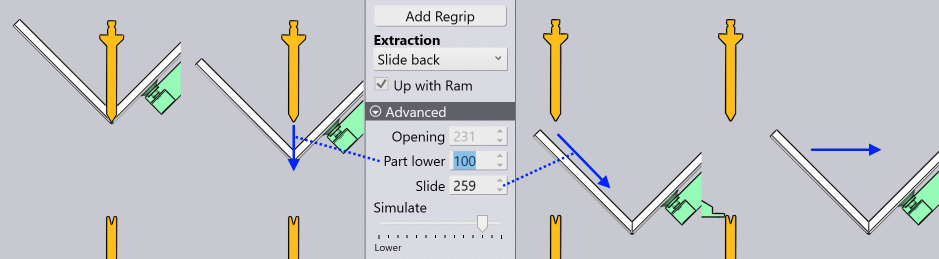
| This extraction can be performed with the Up with Ram switch set on or off. Accordingly you get the option to set the Part lift or the Part lower setting, before the slide-out. |
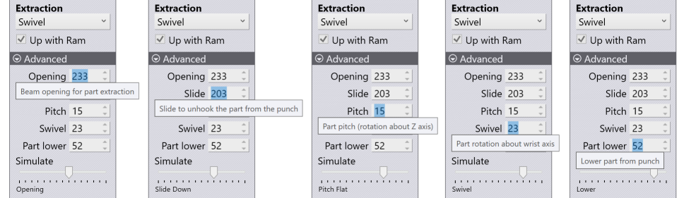
| In all these extraction methods, there are various parameters that are editable. |
As you focus on these parameters to edit them an explanatory tooltip is displayed that helps you understand the meaning of the parameter. More importantly, the simulation is positioned at the appropriate stage, so any changes you make to the parameter are immediately visible on screen. The image below shows how the simulation automatically steps through different stages as you edit different parameters. Simulation phase is displayed at the bottom of the images.

As you change these parameters, any collision or over travel alarms that occur are displayed immediately, so it is easy to adjust these parameters in a very interactive manner.