Modifications of Waypoints
Refer to waypoints topic before going through the below topics.
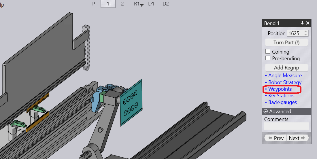
Enable Waypoints Option
-
Select the Bending situation with the desired waypoint
-
Make desired modifications and check the bending process
Understanding the Waypoint Position
The below example shows you the waypoints generated automatically by enabling Bend tooling.
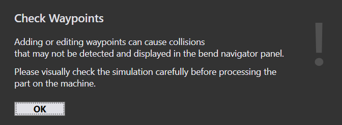
You will be prompted a warning message when you try to make any changes on the waypoint position or inserting a new waypoint.
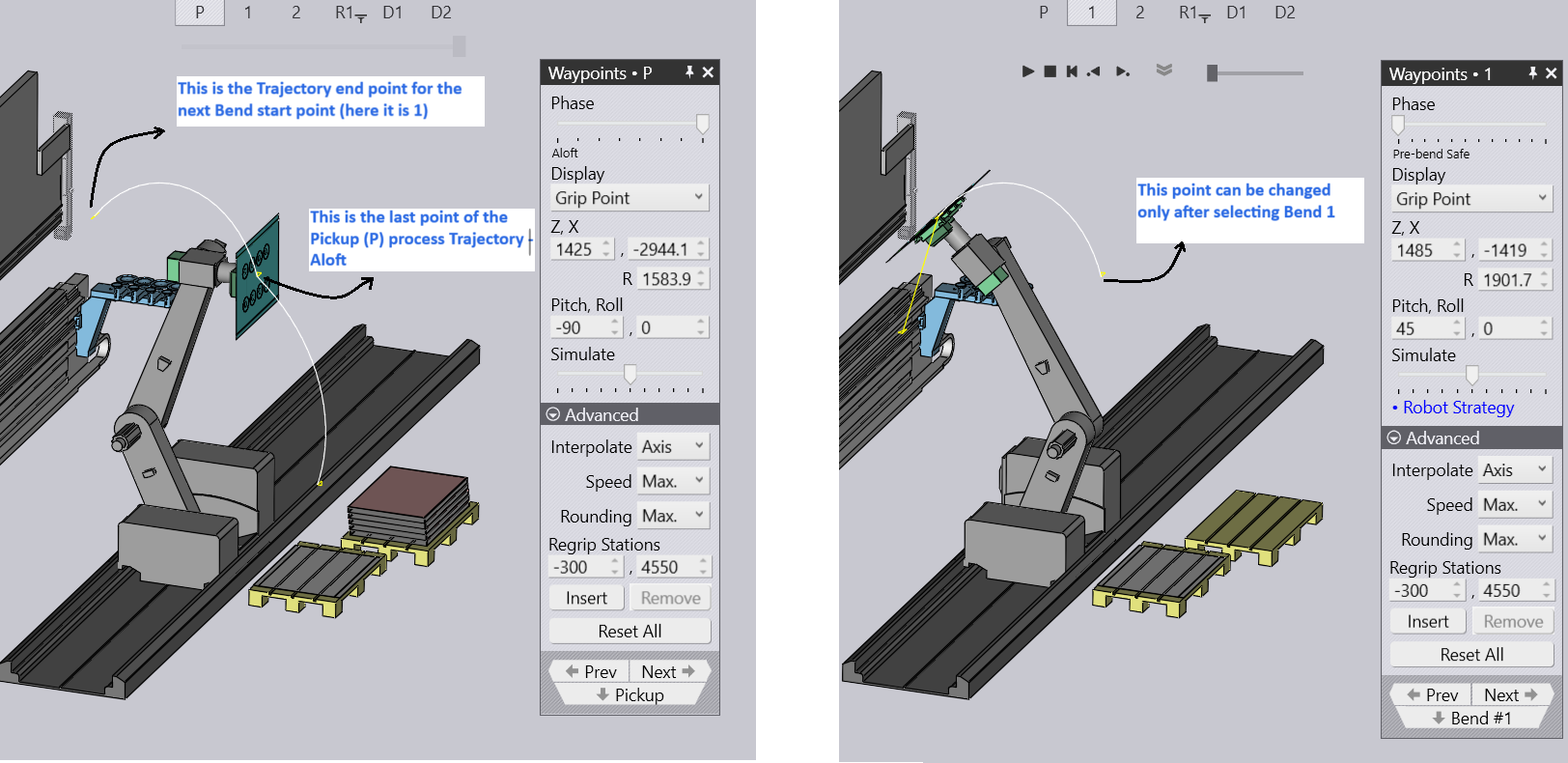
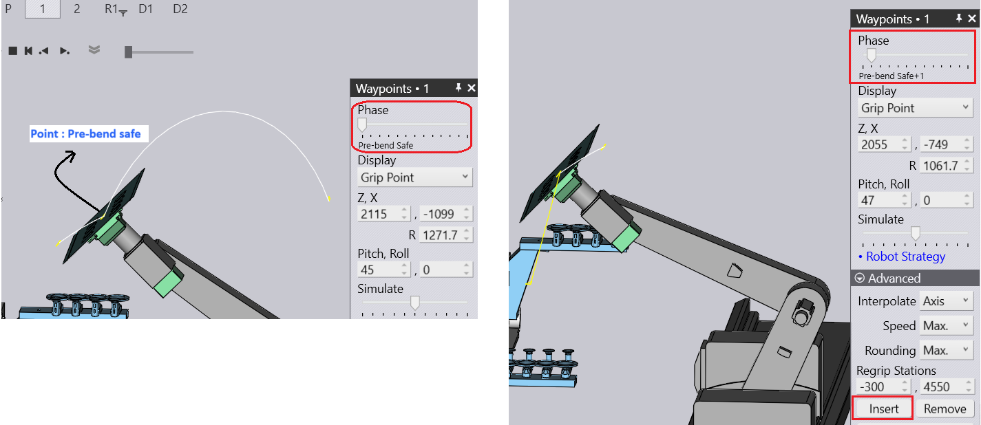
The below image shows you where the Waypoint stands for a particular move. The name stands as Pre-bend safe
Now we try to Insert a new Waypoint and change the values of Z,X R along with the Pith and Roll. A new point will be added with the name Pre-bend safe+1. We can use the same technique to insert points for other phases of Bending.
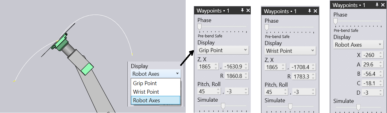
Understanding Display Field
Use the Display field to modify the Waypoint position based on the drop down list - Grip Point, Wrist Point and Robot axes
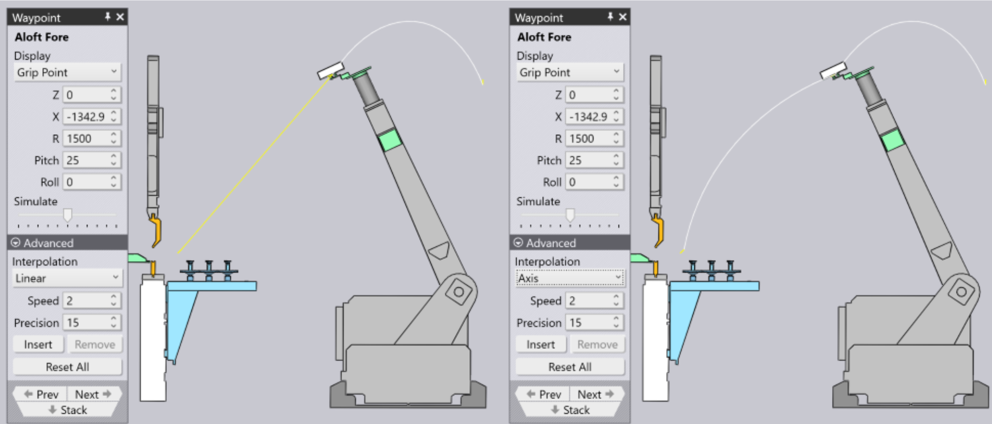
Understanding Interpolation
The linear moves are shown with yellow lines, and the axis-interpolated moves (PTP mode) are shown with white lines. For example, you can see the difference when you switch the waypoint form linear to axis mode: