Editing Microjoints
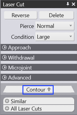
After a part has been tooled, modification of the tooling can be done by the user. Selecting an element of the laser tooling will display the Laser Cut panel, from this, select contour which will open the Contour panel.
-
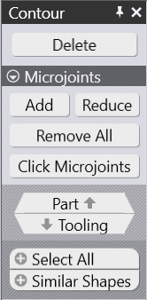
Delete - This will remove the tooling for the selected contour.
-
Add - This option will add or increase microjoints on the contour. Click this option to add a microjoint automatically on the contour.
-
Reduce - This option will remove a microjoint. Reposition the remaining microjoints to be at equal distances.
-
Remove All - This option will delete all microjoints.
-
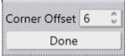
Microjoints - This is a special mode where the user can interactively add/remove microjoints by clicking on the contour. Usual snap points are available to insert microjoints. A special snap point at a standard offset from the corner (entered in the 'Corner Offset' field shown below) is also available.
-
Part - This is a navigational option that will navigate to the part level options.
-
Tooling - This is a navigational option that will navigate you again to Laser Cut panel.
-
Select All - This will select all contours in the part, allowing microjoints to be added/removed.
-
Similar Shapes - This option will select all identical laser cuts in the part. For example, laser tooling of all 10 mm size circles can be selected.
There are two ways to define the microjoint operation:
-
Manual microjoint
-
Auto microjoint
Manual Microjoint
Click on the contour you want to toggle this
setting.
The "Laser Cut" menu will appear (see number 1 in the figure).
Next, you have to check the "Microjoint" field. You can set in the moment just the width of the microjoint.
More settings are available since you access the Contour menu (see number 2 in the below figure). After you add the first microjoint on a
contour, you may now use "Reduce", in order to delete the last created
microjoint. If you have more than one microjoint, you can simply
erase all of them by clicking on Remove all.
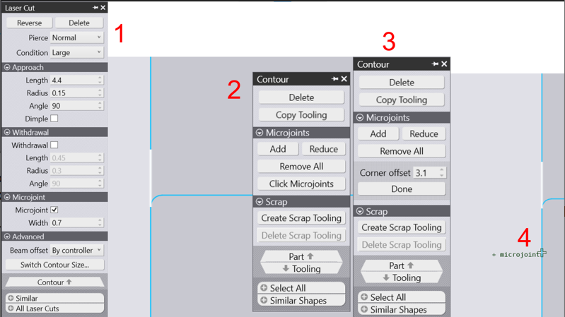
Click Microjoints: Gets you into a mode where you can interactively click on the polyline to insert a microjoint at the point of click. If a microjoint already exists at that point, it will be removed instead. Usual snap points are available to insert microjoints. A special snap point at a standard offset from the corner (entered in the Corner Offset field shown below) is also available. Click on Done button to exit this special mode.
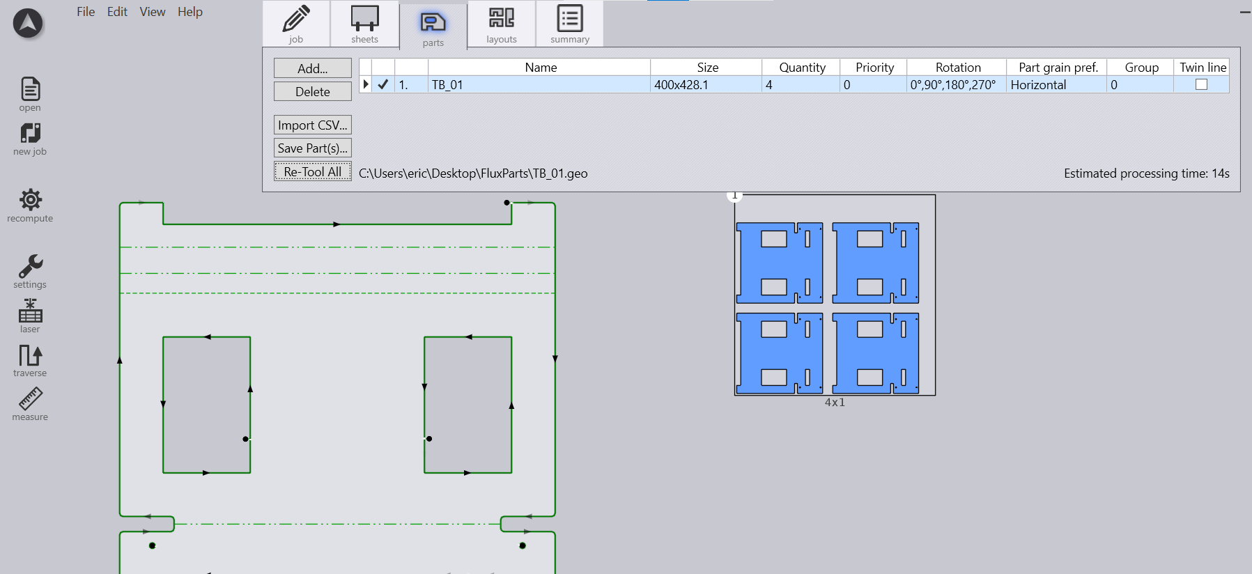
In order to copy the microjoint(s) to other identical pieces, you’ll need to recompute tooling (click on Re-tool all) for all existing parts in the nest job.
Auto Microjoint
Another way to implement a microjoint on a part or to your whole job is through defining the microjoint settings in the Laser Technology Table (LTTs).
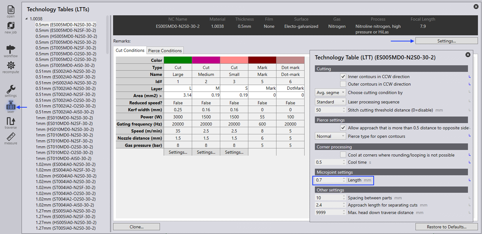
Expand the LTT tree and select laser type to see its parameters.
Click on the Settings option in the top right corner to edit Microjoint setting.
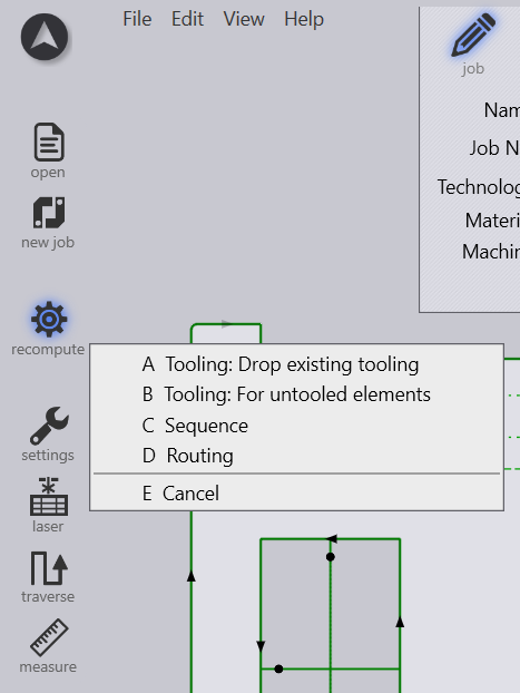
The final step is to update the made changes by recomputing the tooling. (Shortcut key K)
Multiple Microjoints (One, Two or Three)
There is also a possibility in Flux to manage a single, a double and a triple microjoint. In order to access these features, you will need to work on finishing rules one more time. Very important is to make use of the parameter size, in order to select the same type of contour and apply different features (i.e., one microjoint, two microjoints or three microjoints).