Flux Reference Manual

  • Welcome to Flux
  • Introduction
    • Installing the Software
    • The User Interface
    • Part Workflow
    • The Machine Database
  • Cut
    • Basic Workflows
      • Part Workflow
        • Load Part
        • Sketch Mode
        • Measure
        • Modifying Laser Part
        • Nesting
        • Sequence Navigator
        • NC Code Generation
      • Job workflow
        • Create Job
        • Set Laser Technology Table (LTT)
        • Nesting
        • Automatic Part Placement
        • Manual Part Placement
    • Advanced Topics
      • Geometry Import Options
      • Advanced Tooling Options
        • Editing Microjoints
        • TwinLine
        • FlyLine
        • Dimple Approach
        • Remainder Sheets
        • Pie-Slug Circular Holes
        • Avoid Retooling Pierces
        • Finishing Rules
        • Clone LTT
      • Advanced Nesting Features
        • Mirrored Parts
        • Find a Part in Nest Layout
        • Filler parts in Nest Layout
      • Advanced Tooling Optimization
        • Contour Quality
        • Optimizing Stability with Scrap Cutting
        • Optimizing Tilting Behaviour
        • Space Out Slice Cuts to Avoid Collision
        • Minimize Number of Different Layouts
        • Dynamic Level Setting
      • Advanced Menu Options
        • Context Sensitive Menus
        • Hierarchy of Settings
        • Multi-Selections
        • CSV Output
      • Manual Sheet Slicing Cuts
      • Text on Parts
    • Application Settings
      • Cut CAM
        • Layout
          • Nest Settings
          • Sheet
          • Sheet Handling
          • Skeleton Cuts
          • Work Support
        • Laser CAM
          • Sequence
      • Cut Outputs
      • Cut View
  • Bend
    • Basic Steps of Flux Bend
    • Basic Workflow
      • The Main Panel
      • The Workflow Panel
      • Batch processing
      • Modifying the Geometry
      • The Bend Navigator
      • Editing the Bend Solution
        • Editing a Bend
        • Changing the Bending Sequence
        • Editing a Tool Mount
        • Editing a Bend Setup
        • Editing the Back-Gauges
        • Angle Measurement
        • Using a Pre-Bend
        • Editing multiple mounts
        • Adding a Tooling station
      • Recomputing the Bend Solution
      • Generating Bend Outputs
      • Export Bend Report
    • Design of bend parts
      • Min Radius and Flange Length
      • Corner Design
      • Bending Tolerances
      • Selection of Tools
    • Advanced Workflow
      • Preparation of Bend Parts
        • Preparing a 2D drawing
        • Editing a Drawing
        • Add Bending Information as Text to DXF
        • Measuring and changing Outer Dimension
        • Preparing 3D models
        • Preparing an Assembly
        • Component Detection
        • Form Detection
      • Edit Tools
        • Changing Tool Map
        • Change Tool Segmentation
        • Editing Tool-mount Segments
        • Adding a Gap into the Tool
        • Use a Double-V Adapter
        • Tool Priority
        • Creating a Tool
      • Using Bend Deductions
      • Control Visibility
      • Comment Section in Bend Panel
      • Tools/Machine Tonnage Check
    • Settings
      • Application Settings
        • Bend CAM
          • Bend Outputs
          • Bend View
          • Bend Cell
      • Database Settings
        • Materials
        • Machines
        • Bend Tools
        • Bend Deductions
        • Bend grippers
        • Forms/Components
      • Bend Settings
      • Machine Defaults
  • Robotic Bending
    • Overview of Robotic Bending
    • Basic Steps of Robotic Bending
    • Workflow
      • Part Pickup
        • Pickup from a Pallet
        • Pickup from a Dispenser
      • Insertion Strategy
      • Bending Strategy
      • Regripping (RG) Stations
        • Re-Grip Stations
        • Methods of Regripping
        • Adding ReGrip
        • Modify ReGrip Position
        • Remove ReGripping
        • Regrip with a Jaw Gripper
        • Gripper Panel & Suction Panel
      • Extraction Strategy
      • Part Deposit
        • Adapt Part Deposit
        • Adding Parts & Stacks
          • Deposit Panel
          • Add Separator Sheets
          • Lock Part-Rest
          • Repeat Grid Field
          • Deposit Sequence
        • Deposit Pattern Types
      • Waypoints
        • Adapt WayPoints
        • Display Waypoints
        • Simulate Waypoints
        • Modify WayPoints
        • Properties of Waypoints
    • Advanced Topics
      • Cell Configuration
        • Track Setup
        • Gripper Inventory
        • BendCell settings
      • Gripper Configuration
        • Create/ Edit a Gripper
        • Import Gripper from DXF
    • Troubleshooting Bend Errors
      • Part Pickup Error
      • Collisions with Machine
      • Overtravel of Axis
      • Modifications of Waypoints
      • Collisions while Insertion and Extraction
  • Fold
    • Switching to Fold CAM
    • The Fold View
    • Editing Operations
      • Editing a Bend-Op
      • Editing a Side/Section
      • Changing the Sequence
      • Editing the Blank-holders
      • Editing the Gauging
      • Editing the Blades
      • Editing the Loading
      • Editing the Unloading
    • Tool Management
    • Fold CAM Summary
  • Generic Application Settings
    • Drawing
      • Layers
      • Dimensions
      • View
    • Environment
    • Import/Export
  • Flux Reports
    • Report Designer
    • Fields, Pictures and Tables
    • Bands (sub-reports)
    • Labels, Bitmaps and Shapes
  • Appendix
    • Supported 3D Formats
    • Separator Sheet DXF
Flux Reports
/
Labels, Bitmaps and Shapes

Labels, Bitmaps and Shapes

In addition to the data that comes from the part, reports may need some other adornments - company logos, standard messages and simple geometric elements like divider lines. These are accessed from the Sys data source.
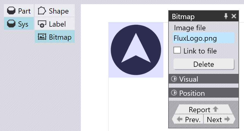
Inserting a Bitmap

You can add a bitmap (like a company logo, for example) by choosing Sys > Bitmap. Pick any image file to insert it into the report. It can then be resized or positioned as needed. If you turn on the Link to File, Flux will just store a link to the image file in the report template. Else it will store a copy of the entire bitmap in the report template.
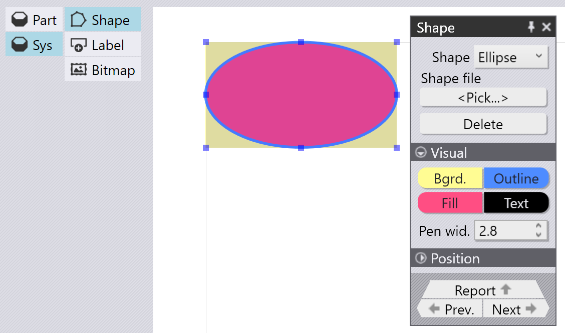
Bitmap

Inserting a Shape

Use the Sys > Shape option to insert a simple geometric shape into the report. You can set the background, fill and outline colors separately, and you can control the outline thickness for the shape.

Shape

In addition to these simple shapes, you can also insert much more complex shapes by reading them in from a 2D file (like GEO, DXF or DWG). Choose the From File option in the shape, and then pick a 2D drawing file.[1]. All closed outlines in the file are selected and filled with the selected fill color and outlined with the selected pen.

Shape 2

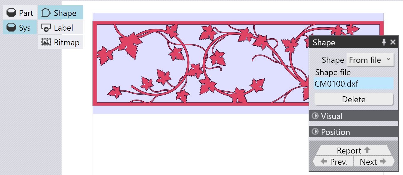
Such shapes inserted from DXF and bitmaps often serve similar purposes. However, the shapes inserted from a DXF file are vector images and scale very well, even if the report is being printed at high resolution. On the other hand, bitmaps may not scale well to high resolutions.

Inserting a Label

Labels are inserted automatically when you add a field or a table. However, you can insert a standalone label (or any other fixed text) by choosing Sys > Label

These items (bitmaps, labels and shapes) are available for insertion even within a sub-report or band. They are then repeated as many times as the band is rendered.


1. After the shape is inserted, the DXF/GEO file is no longer needed; the closed outlines from that file are improted in and stored as part of the report template.

Contents

  • Inserting a Bitmap
  • Inserting a Shape
  • Inserting a Label
Bands (sub-reports) Appendix

      Copyright © 2023 by Metamation. All rights reserved.

    Compiled by Bento