Flux Reference Manual

  • Welcome to Flux
  • Introduction
    • Installing the Software
    • The User Interface
    • Part Workflow
    • The Machine Database
  • Cut
    • Basic Workflows
      • Part Workflow
        • Load Part
        • Sketch Mode
        • Measure
        • Modifying Laser Part
        • Nesting
        • Sequence Navigator
        • NC Code Generation
      • Job workflow
        • Create Job
        • Set Laser Technology Table (LTT)
        • Nesting
        • Automatic Part Placement
        • Manual Part Placement
    • Advanced Topics
      • Geometry Import Options
      • Advanced Tooling Options
        • Editing Microjoints
        • TwinLine
        • FlyLine
        • Dimple Approach
        • Remainder Sheets
        • Pie-Slug Circular Holes
        • Avoid Retooling Pierces
        • Finishing Rules
        • Clone LTT
      • Advanced Nesting Features
        • Mirrored Parts
        • Find a Part in Nest Layout
        • Filler parts in Nest Layout
      • Advanced Tooling Optimization
        • Contour Quality
        • Optimizing Stability with Scrap Cutting
        • Optimizing Tilting Behaviour
        • Space Out Slice Cuts to Avoid Collision
        • Minimize Number of Different Layouts
        • Dynamic Level Setting
      • Advanced Menu Options
        • Context Sensitive Menus
        • Hierarchy of Settings
        • Multi-Selections
        • CSV Output
      • Manual Sheet Slicing Cuts
      • Text on Parts
    • Application Settings
      • Cut CAM
        • Layout
          • Nest Settings
          • Sheet
          • Sheet Handling
          • Skeleton Cuts
          • Work Support
        • Laser CAM
          • Sequence
      • Cut Outputs
      • Cut View
  • Bend
    • Basic Steps of Flux Bend
    • Basic Workflow
      • The Main Panel
      • The Workflow Panel
      • Batch processing
      • Modifying the Geometry
      • The Bend Navigator
      • Editing the Bend Solution
        • Editing a Bend
        • Changing the Bending Sequence
        • Editing a Tool Mount
        • Editing a Bend Setup
        • Editing the Back-Gauges
        • Angle Measurement
        • Using a Pre-Bend
        • Editing multiple mounts
        • Adding a Tooling station
      • Recomputing the Bend Solution
      • Generating Bend Outputs
      • Export Bend Report
    • Design of bend parts
      • Min Radius and Flange Length
      • Corner Design
      • Bending Tolerances
      • Selection of Tools
    • Advanced Workflow
      • Preparation of Bend Parts
        • Preparing a 2D drawing
        • Editing a Drawing
        • Add Bending Information as Text to DXF
        • Measuring and changing Outer Dimension
        • Preparing 3D models
        • Preparing an Assembly
        • Component Detection
        • Form Detection
      • Edit Tools
        • Changing Tool Map
        • Change Tool Segmentation
        • Editing Tool-mount Segments
        • Adding a Gap into the Tool
        • Use a Double-V Adapter
        • Tool Priority
        • Creating a Tool
      • Using Bend Deductions
      • Control Visibility
      • Comment Section in Bend Panel
      • Tools/Machine Tonnage Check
    • Settings
      • Application Settings
        • Bend CAM
          • Bend Outputs
          • Bend View
          • Bend Cell
      • Database Settings
        • Materials
        • Machines
        • Bend Tools
        • Bend Deductions
        • Bend grippers
        • Forms/Components
      • Bend Settings
      • Machine Defaults
  • Robotic Bending
    • Overview of Robotic Bending
    • Basic Steps of Robotic Bending
    • Workflow
      • Part Pickup
        • Pickup from a Pallet
        • Pickup from a Dispenser
      • Insertion Strategy
      • Bending Strategy
      • Regripping (RG) Stations
        • Re-Grip Stations
        • Methods of Regripping
        • Adding ReGrip
        • Modify ReGrip Position
        • Remove ReGripping
        • Regrip with a Jaw Gripper
        • Gripper Panel & Suction Panel
      • Extraction Strategy
      • Part Deposit
        • Adapt Part Deposit
        • Adding Parts & Stacks
          • Deposit Panel
          • Add Separator Sheets
          • Lock Part-Rest
          • Repeat Grid Field
          • Deposit Sequence
        • Deposit Pattern Types
      • Waypoints
        • Adapt WayPoints
        • Display Waypoints
        • Simulate Waypoints
        • Modify WayPoints
        • Properties of Waypoints
    • Advanced Topics
      • Cell Configuration
        • Track Setup
        • Gripper Inventory
        • BendCell settings
      • Gripper Configuration
        • Create/ Edit a Gripper
        • Import Gripper from DXF
    • Troubleshooting Bend Errors
      • Part Pickup Error
      • Collisions with Machine
      • Overtravel of Axis
      • Modifications of Waypoints
      • Collisions while Insertion and Extraction
  • Fold
    • Switching to Fold CAM
    • The Fold View
    • Editing Operations
      • Editing a Bend-Op
      • Editing a Side/Section
      • Changing the Sequence
      • Editing the Blank-holders
      • Editing the Gauging
      • Editing the Blades
      • Editing the Loading
      • Editing the Unloading
    • Tool Management
    • Fold CAM Summary
  • Generic Application Settings
    • Drawing
      • Layers
      • Dimensions
      • View
    • Environment
    • Import/Export
  • Flux Reports
    • Report Designer
    • Fields, Pictures and Tables
    • Bands (sub-reports)
    • Labels, Bitmaps and Shapes
  • Appendix
    • Supported 3D Formats
    • Separator Sheet DXF
Robotic Bending
/
Overview of Robotic Bending

Overview of Robotic Bending

Bend Navigator

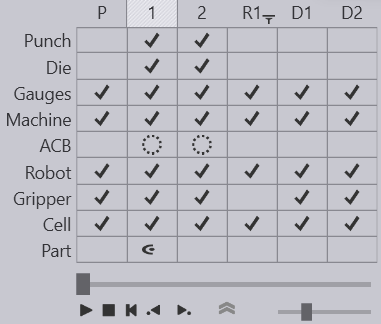
The Navigator panel on the top displays the different stages of bend simulation. A stage is either a bend operation, or a robot operation such as a Pickup, Robotic Bending, Regrip and Deposit. These are assigned names like P,R1, D1, D2 etc.

Operation Short name

Pickup

P

Bending

1, 2, 3,…​

Regrip

R1, R2,…​

Deposit

D1, D2,…​

Following are the shortcut keys assigned to various stages in the bend navigator:

newitem234
Shortcut Explanation

PageUp PageDown

Switch to the previous or next stage in the simulation (for example, previous or next bend).


Switch to the next or previous phase within the same stage. For example, phases in bending are like part insert, gauge-retract, bend, beam-open etc.

Spacebar

Start/stop the simulation.

Z

Expand/collapse the navigator panel.

Responsive Panels

Usually the desired component is selected by clicking on it.

newitem615

Stage Panels

Each of the stages like the Pickup, Bend, Regrip or Deposit has a stage panel where you can edit the basic settings for that stage. See below image for examples panels:

stage

You can navigate between these panels for each stage also by clicking the Previous Prev and Next Next buttons that appear on each of them.

Shortcut key Meaning

E E

Open the stage panel for the current stage (one of the panels shown above).

Left click twice on header (in the bend sequence navigator)

Clicking on the column header (like P, 1, 2, R1, 3, 4, D1,…​) in the navigator will switch the simulation to that stage. Clicking again will open the stage panel.

Tooling and Gauging Panels

There are panels to edit the punch, die and gauge status of the tooling. These are displayed below and can be accessed by clicking on the punch, die or back-gauges.

gauge
Shortcut key Meaning

E B

Open the Back-gauge panel

Left click on back-gauge

Open the Back-gauge panel

E D

Open the Die panel

Left click on the die

Open the Die panel

E P

Open the Punch panel

Left click on the punch

Open the Punch panel.

Pickup Panels

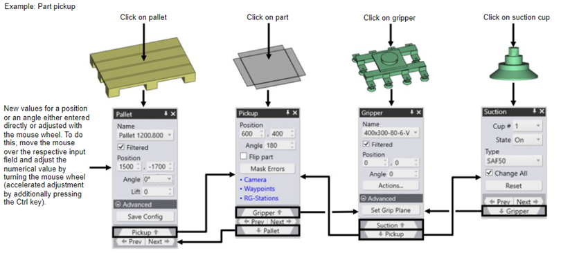
From the Pickup panel, there are several linked panels that can be opened by clicking the navigation links on the bottom, or the hyperlinks in blue.

pickup
newitem235
Figure 1. Robot with Gripper
Shortcut key Meaning

E E

Open the Pickup panel

Left click a blank on the pallet

Open the Pickup panel

E G

Open the Gripper panel (gripper position for this stage)

Left click on the gripper (or robot’s C axis)

Open the Gripper panel

Left click on the camera

Open the Camera panel

Left click on a suction cup of the gripper

Open the Suction panel (suction cup settings for this part)

Left click on the pickup pallet

Open the Pallet panel (to move/rotate the pickup pallet).

Deposit Panels

The deposit panels follow a similar logic to the Pickup panels, and are interlinked in the same way (they are a bit simpler since you do not have Camera settings, or Gripper settings for a part deposit).

Shortcut key Meaning

E E (press E key twice)

Open the Deposit panel

Left click on part on the deposit pallet

Open the Deposit panel

Left click on the deposit pallet

Open the Pallet panel (to move/rotate the deposit pallet)

Robot Panels

The following screens are for the BendMaster waypoints' settings:

robot

The image above shows the different panels related with pickup. These panels are all accessible from the bend panel (or other stage panels) using the hyperlinks as seen above. In addition, you can also access these panels by clicking on various parts of the bending cell, or using shortcuts.

Shortcut key Meaning

E W

Open the Waypoints panel

Left click on the robot rail

Open the Waypoints panel

E R

Open the Robot Strategy panel (applicable only for bend column)

Left click on the X,A or B axes of robot

Open the Robot Strategy panel

Left click on the regrip stations

Open the Regrip stations panel

Contents

  • Bend Navigator
  • Responsive Panels
  • Stage Panels
  • Tooling and Gauging Panels
  • Pickup Panels
  • Deposit Panels
  • Robot Panels
Robotic Bending Basic Steps of Robotic Bending

      Copyright © 2023 by Metamation. All rights reserved.

    Compiled by Bento