Adding Parts & Stacks
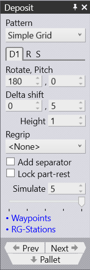
Deposit Panel
The Deposit panel controls most of the settings for the Deposit. The settings available here depend on the pattern that is being used. You can switch between some of these patterns, though not all deposit patterns are suitable for all parts. For example, the Drop to Basket pattern is usable only if you are using the mechanical gripper with a small part.
Deposit tab D1 (and optionally D2)
There are several deposit patterns available (Simple, Alternating, Weave, Basket etc). Some of these patterns (Alternating, Weave) use parts deposited in two different orientations. The orientation and other settings for these parts are edited in the D1 and optionally the D2 tabs (these also correspond directly with the D1 and D2 deposits on the main navigation bar on the top).
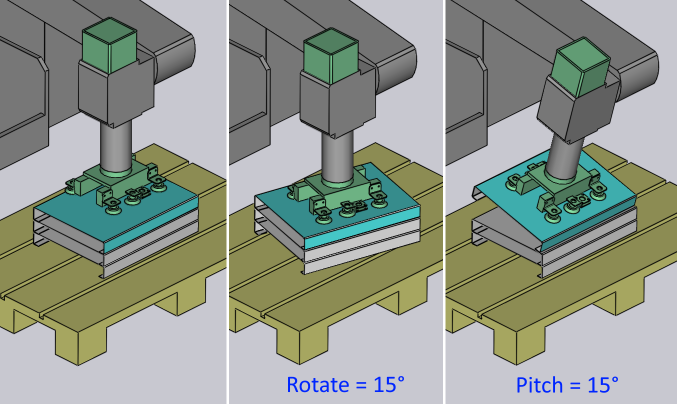
Rotate and Pitch
The Rotate and Pitch settings control the orientation of the part at the point of drop. The Rotate setting (also known as yaw) turns the part around the wrist local vector, while the Pitch axis rotates the part about the machine Z axis.
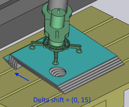
Delta Shift
The Delta Shift vector is used to shift each successive part in the deposit relative to the part underneath. You can see a shift of +15mm in the X direction below, used to stack the parts tightly against each other in a stable manner:
The Height parameter controls the height above the stack from which the part is released (the part falls by this distance when coming to rest on the stack).
Regrip
Click on the Regrip drop down menu and select <Add> to add a new regrip (R1) before the deposit - this allows you to deposit the part upside down, or with a different gripper orientation that was used for the last bend. You can also choose any other existing regrip added earlier which will be listed in the drop-down. Selecting <None> will remove the regrip used.
Add Separator
The Add separator setting is used to place a separator sheet after each layer of the deposit so the next set of parts can be deposited on a flat surface again.
Lock part-rest
The Lock art-rest setting is used to lock the rest-orientation of the part to the drop-orientation.