Editing the Loading
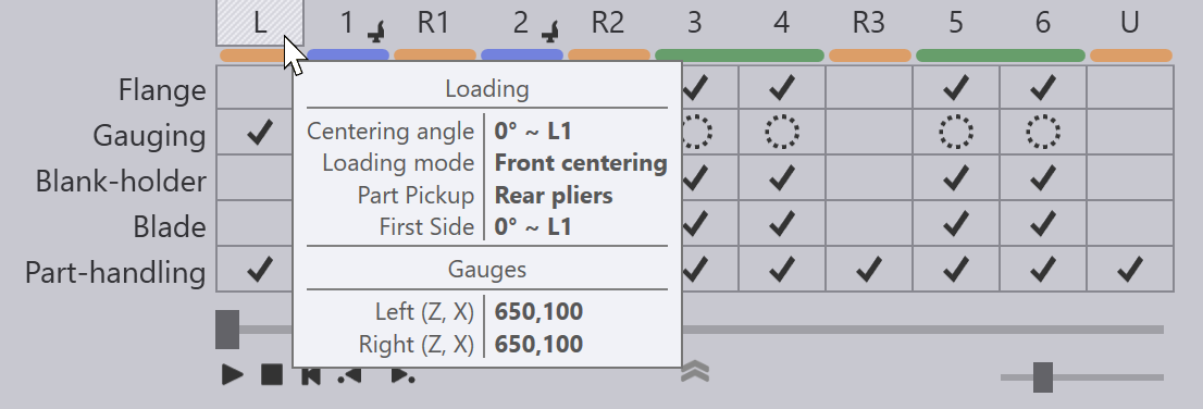
The Loading operation for an automated panel-bender (like the TBC-7030 or the TBC-7020) can be edited by clicking twice on the loading cell in the navigator on the top. This is the cell labelled L. The first click selects the load operation, and the second click brings up the load panel.
7030 (Front-Loading)
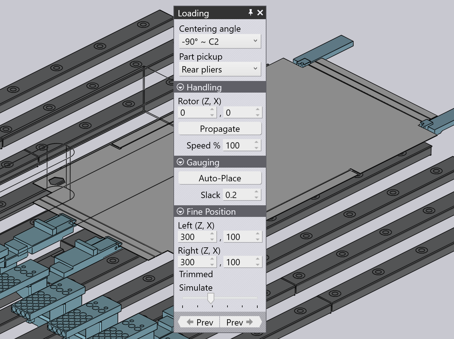
The Loading panel for a front-loading 7030 machine looks like this:
-
The Centering angle setting specifies the part orientation during the centering operation. Note that this is the side facing into the machine, and is therefore exactly opposite to the side actually referencing the front gauges. In this example, the side C2 faces into the machine (and the side C1 at +90 degrees is used for gauging). This setting displays a list of orientations that are suitable for the initial centering.
-
The Part Pickup selector lets you choose if the part is picked up using the vacuum suction cups or using the rear pliers. (This is displayed only if both choices are available. Some parts will be too small to be picked up by the vacuum gripper, and some parts will be too large to be picked up by the rear pliers).
-
The Simulate slider at the bottom can be used to simulate the different steps of the initial centering process.
Gauging section
This collapsible section lets you cycle through various gauge placements.
-
The Auto-Place setting can be used to switch between different gauge placements. Depending on the part geometry, there could be multiple locations on the edge of the part where various types of corner or notched gauging could be done. Clicking this button repeatedly will cycle through all these options. (As you do this, you will note the actual gauge positions getting updated in the Fine Position section).
-
The Slack setting is used to add an additional gap (in the Z direction) between the gauges. It can be used to facilitate gauging in the case of parts that may not be trimmed exactly to size.
Handling section
This section sets up the rotation position and other handling options during the centering cycle.
-
The Rotor (Z, X) settings control the rotor position (position of the rotation center), and these are measured relative to the part center in the centering orientation.
-
Click on Propagate to use the same rotation center for processing all the sides. Typically, Flux will try to optimize the rotation centers to minimize the number of double-rotations required. However, if you manually adjust the rotation center using the setting above, you could use this to button to try further optimization.
-
The Speed % setting controls the rotation speed (as a percentage of the maximum possible speed).[1]
Fine Position section
This collapsible section lets you edit the gauge positions manually. Typically this should be rarely required - most of the time, the initial selection of gauging position is optimal. And in other situations, a few clicks of the Auto Place button mentioned above should position the gauges correctly. The Fine Position settings are only for those rare cases or unusual geometry where Flux cannot find any gauging solutions.
-
The Left (Z, X) settings let you control the position of the left gauge. The Z position is measured from the center-line, while the X position is measured from the edge of the part in the X direction. As you adjust this setting, the gauges move, and you may see collisions, or gauge-not-engaged errors.
-
The Right (Z, X) settings control the position of the right gauge.
-
The Trimmed indication in the display switches between Trimmed, Untrimmed, or Diagonal to indicate the type of gauging in effect
7030 + KB40 (Front / Rear Loading)
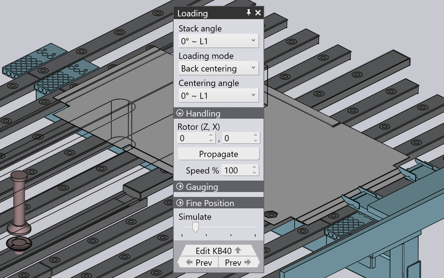
For a 7030 equipped with a KB40, there are more options available during the loading:
-
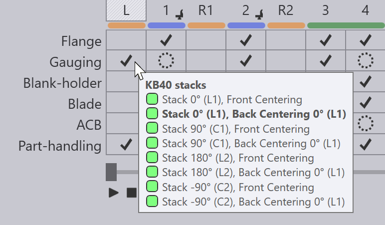
Use the Stack angle setting to select a particular orientation of the part on the KB40 pallet. You can then set up the loading mode (front or back) and the centering angle for that particular stack angle. The NC code (XML) generated by Flux has the centering settings for each of the various stack angles embedded in it. Depending on the actual stack angle, the appropriate setting is used. You can inspect all the stack angles that are programmed by pointing at the Gauging cell:
-
The Loading mode setting is used to select between Back centering and the Front centering modes.
-
The Centering angle setting is used to select the orientation of the part during the initial centering. If the loading mode is set to front centering, then the centering angle is the same as the stack angle (since no rotation is done before the part is pushed against the front gauges). If the loading mode is set to back centering, then the centering angle is one of these:
-
The stack angle : the part is centered first, and then pulled back and rotated to the initial side orientation.
-
The first side angle : the part is rotated to the same orientation as the initial side orientation before centering.
-
The Handling, Gauging and the Fine Position sections are similar to the corresponding sections from the 7030 (see section above), except that they may refer to the positions of the back-gauges or the front-gauges (depending on the Loading mode setting).
7020 (Ergo-Centering)
On the 7020 panel bender, there are no front-gauges. The initial centering happens against the rear gauges, and the panel looks like this:
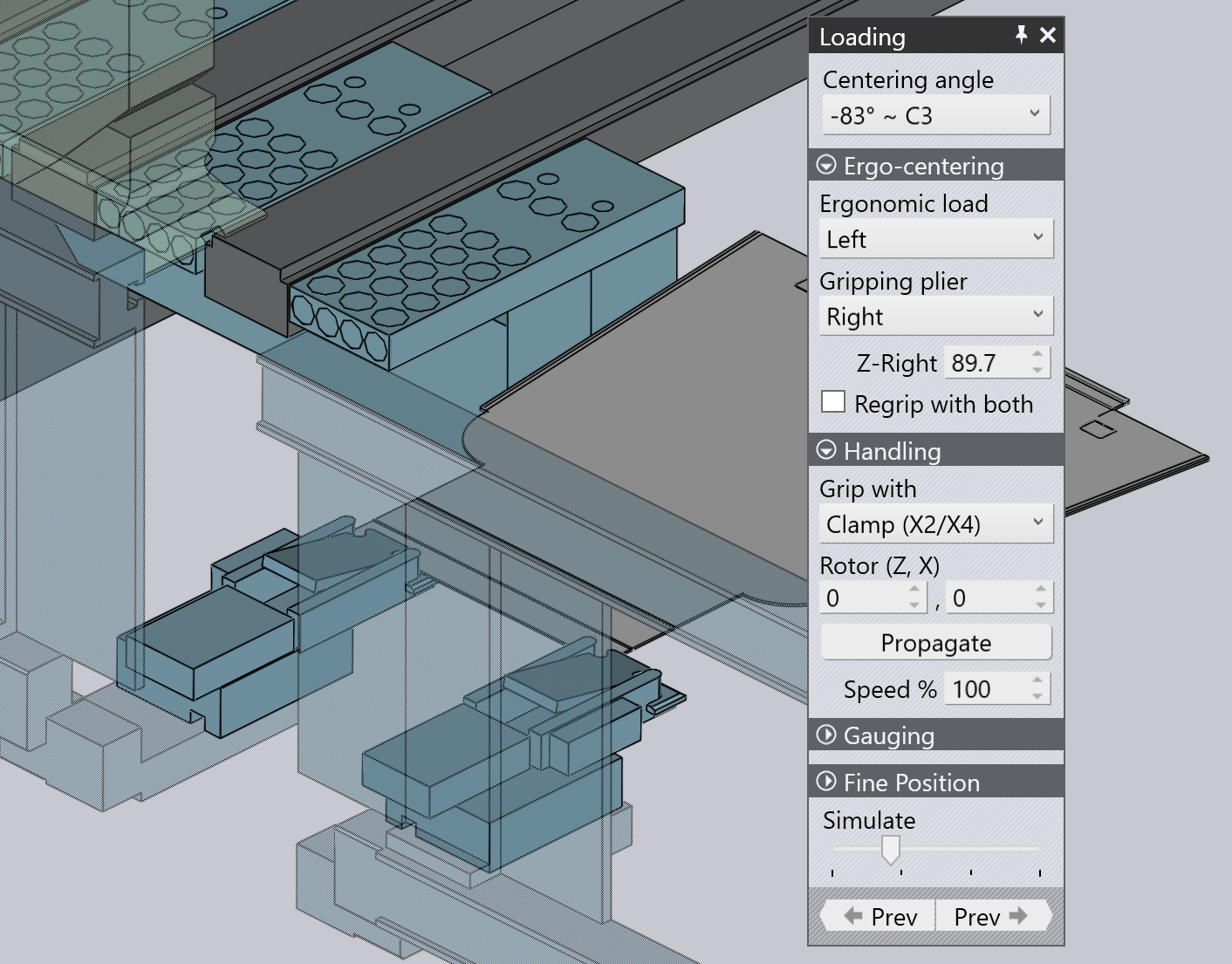
The Centering Angle setting is used to select the orientation of the part during the initial centering. This can be different from the first-side orientation - in this case, the part is centered, then pulled back and rotated before the first side is processed.
Ergo-Centering section
This section is used to select if ergonomic centering is enabled, and is then used to program ergonomic centering.
-
If the Ergonomic load setting is set to <No>, then no ergonomic centering happens. The part is loaded with the gauges in the center (in processing position). If this is set to Left or Right, then an ergonomic centering cycle is programmed.
-
The Gripping plier selects which of the two pliers is used for gripping the part and pulling it to the center (the other plier is used for referencing a corner of the part). Typically, if the ergonomic centering happens on the left side, the right plier is used for gripping, and vice-versa.
-
The Z-Right (or Z-Left) setting controls the position of this gripping plier. As you slide it along the part, the X position of the plier is automatically adjusted so it can grip the leading edge of the part.
-
The Regrip with both switch can be used to provide more stability during the transport of the part to the center of the machine. If this is turned on, then the other plier is also used to grip the part edge while it is pulled into the machine.
-
The Z-Regrip setting (displayed only if the Regrip with both switch is on), sets up the position of the second plier when it is gripping the part.
Handling section
This section is almost similar to the handling section for the 7030 machine.
-
The Grip with setting is used to select whether the part is gripped with the vacuum manipulator (X3) or with the rotary clamps (X2/X4) during the centering cycle.
-
The Rotor (Z, X) is the position of the rotary clamp (relative to the part center) when the part is held / rotated during the centering cycle. If that side is subsequently processed using the rotary clamp (based on the Grip with setting above), this is also the position at which the clamp holds the part during the side processing.
The Gauging and the Fine Position settings are similar to the ones used for the 7030 (see section above), except that they now control the positions of the back-gauges rather than the front-gauges.