Editing the Unloading
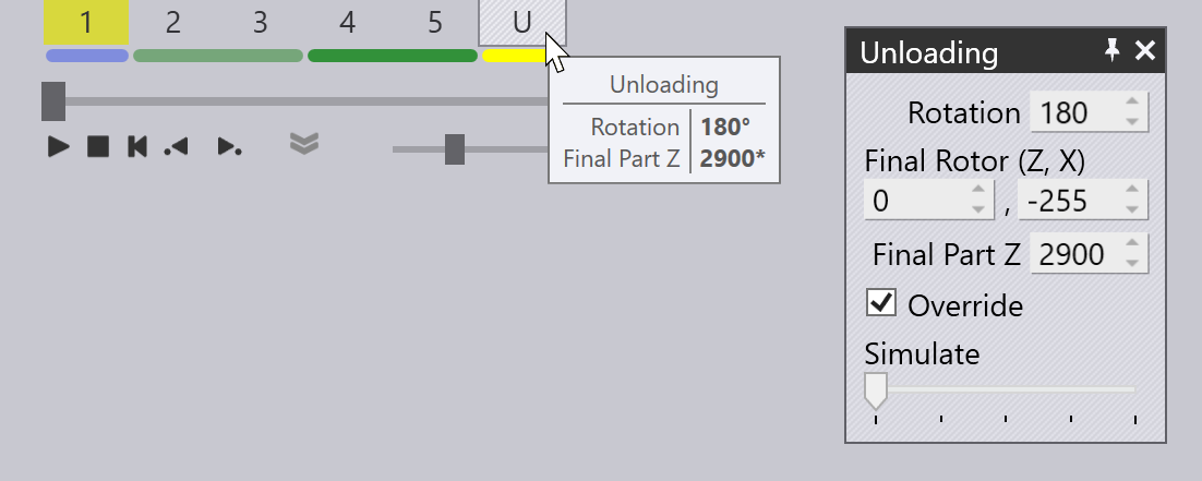
The Unloading operation for an automated panel-bender (like TBC-7030 or the TBC-7020) can be edited by clicking twice on the unloading cell in the navigator on the top. This is the cell labelled U. Clicking twice on this cell (first to select the unloading operation, and then to open the panel) displays this:
Unloading Panel
Here are the settings available in the Unloading panel. Depending on the context, only some of these settings may be visible or editable (for example, if you are not rotating the part before unloading, the settings related to the rotation center will not appear).
-
The Rotation setting on the unloading panel is used to control the rotation of the part before unloading. This is measured relative to the last processing side, so a value of 0 here means the part is unloaded directly without any rotation.
-
The Final Part Z and Override settings control the final Z position of the part-center. If there is no override, the machine will push the part out as much as possible based on the stroke limitation of the X2 or X4 axis (whichever is used to unload the part). You can restrict this movement by turning on the Override switch and setting a value for the final part position. (Typically, this is done to prevent the part sticking out too much from the front edge of the table at the end of the unloading).
-
For small parts, the option of Back Unloading may be available (only on the 7030). If this is turned on, the part is pushed back further with the back-face of the manipulator (see images below).
-
The Final Rotor (Z, X) settings control the Z, X positions of the rotor relative to the part center at the end of all the unloading rotations - in other words, at the orientation the part is during the discharge.
-
The Initial Rotor (Z, X) settings are displayed only if the selected Final Rotor positions require two rotations to achieve after the processing of the final side. In this situation, these offsets specify the rotor position (relative to the part center) during the first of these two rotations.
Some examples of various unloading cycles will help clarify these settings.
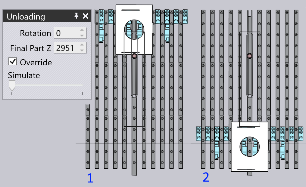
Simple unloading with no rotation
The images below show a simple unload cycle with no rotations (the Rotation value is set to 0). In this cycle, the final part position is overridden to stop the part short. Flux normally computes this necessity for override based on whether the part would stick out too much from the edge of the table, but you can subsequently turn it on or off, and then adjust the final delivery position of the part.
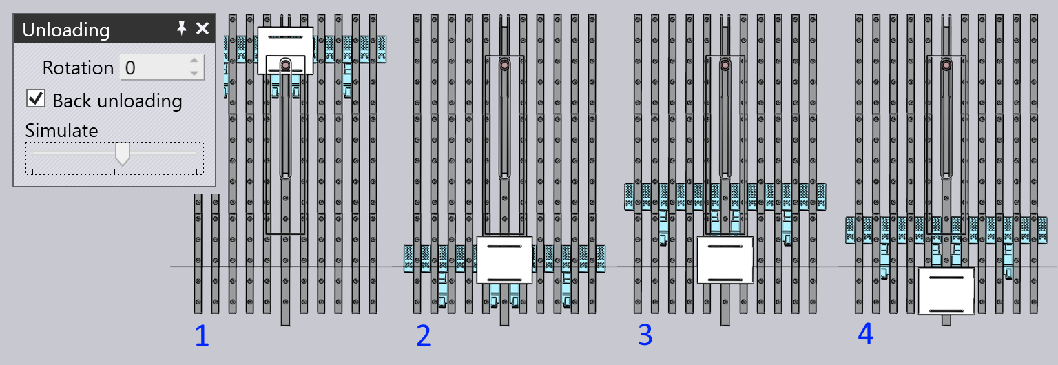
Simple cycle with back-unloading
Here is a part where the Back unloading cycle is enabled (this is available only for small parts). In step 2, the part is released by the vacuum gripper, which then backs up behind the part (step 3), and then pushes the part closer to the operator using the back-face (step 4).
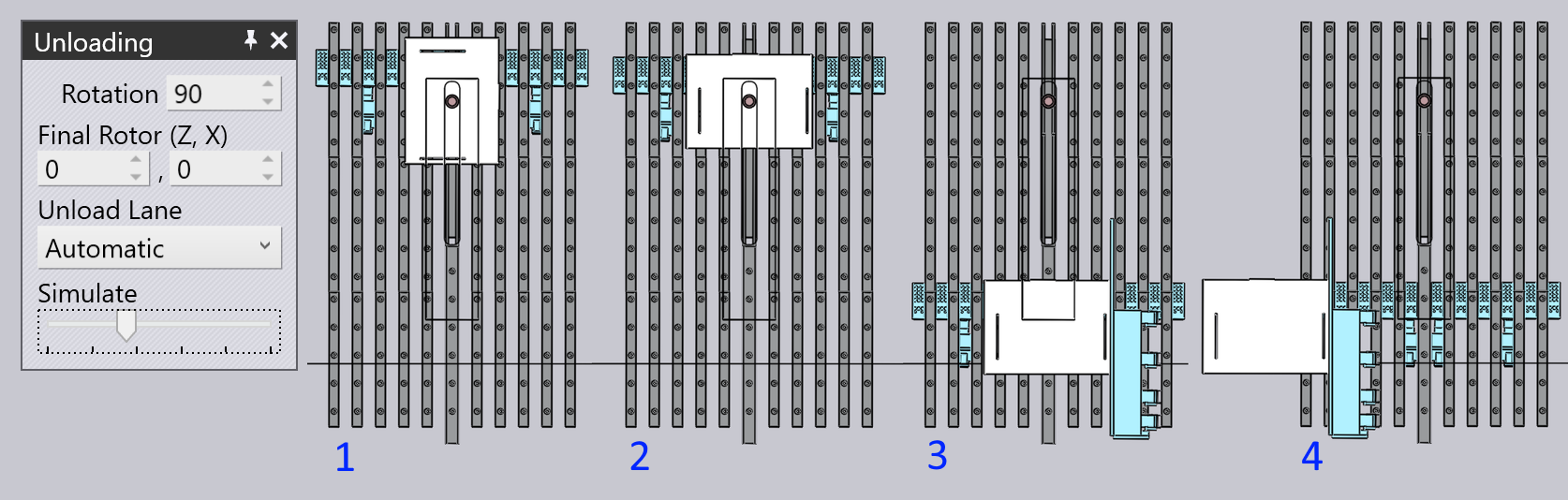
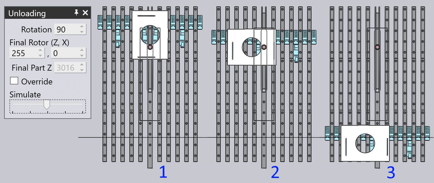
Single rotation of 90 degrees
The example below shows an unloading with a single 90 degree rotation. In step 1, the part is pulled back after the last bend, and clamped by the rotor. The rotor then rotates the part 90 degrees. At the end of the rotation (Step 2), you can see that the rotor is at the specified Final Rotor (Z,X) position relative to the part center: (255, 0).
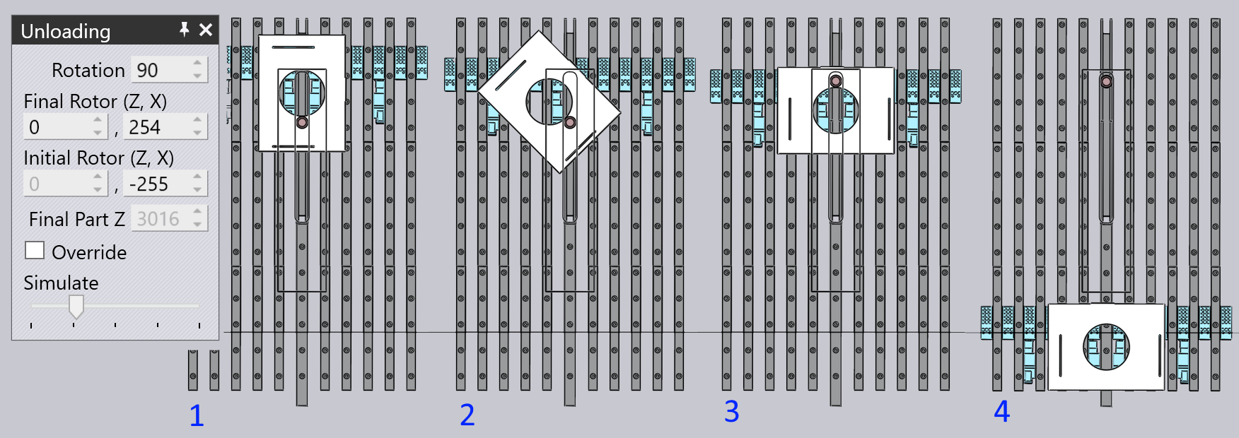
90 degree two-stage rotation
In this example, a 2-stage rotation is required because of the specification of the final rotor position.
-
In Step 1, the part reaches the Initial Rotor position of 0, -255 and is clamped by the rotor.
-
In Step 2, the intermediate rotation position is reached, and the rotor shifts to re-clamp the part.
-
In Step 3, the Final Rotor position of 0, 254 is reached.
-
The part is then released from the rotor and unloaded towards the user in Step 4.
Unloading to a KB40 lane
If a KB40 loader/unloader attachment is fitted, then the option to unload to a specific KB40 lane is available. You can choose between an automatic lane selection, select one of the UZ1 or UZ2 lanes (provided the part is narrow enough to fit with the lane / lanes).