Flux Reference Manual

  • Welcome to Flux
  • Introduction
    • Installing the Software
    • The User Interface
    • Part Workflow
    • The Machine Database
  • Cut
    • Basic Workflows
      • Part Workflow
        • Load Part
        • Sketch Mode
        • Measure
        • Modifying Laser Part
        • Nesting
        • Sequence Navigator
        • NC Code Generation
      • Job workflow
        • Create Job
        • Set Laser Technology Table (LTT)
        • Nesting
        • Automatic Part Placement
        • Manual Part Placement
    • Advanced Topics
      • Geometry Import Options
      • Advanced Tooling Options
        • Editing Microjoints
        • TwinLine
        • FlyLine
        • Dimple Approach
        • Remainder Sheets
        • Pie-Slug Circular Holes
        • Avoid Retooling Pierces
        • Finishing Rules
        • Clone LTT
      • Advanced Nesting Features
        • Mirrored Parts
        • Find a Part in Nest Layout
        • Filler parts in Nest Layout
      • Advanced Tooling Optimization
        • Contour Quality
        • Optimizing Stability with Scrap Cutting
        • Optimizing Tilting Behaviour
        • Space Out Slice Cuts to Avoid Collision
        • Minimize Number of Different Layouts
        • Dynamic Level Setting
      • Advanced Menu Options
        • Context Sensitive Menus
        • Hierarchy of Settings
        • Multi-Selections
        • CSV Output
      • Manual Sheet Slicing Cuts
      • Text on Parts
    • Application Settings
      • Cut CAM
        • Layout
          • Nest Settings
          • Sheet
          • Sheet Handling
          • Skeleton Cuts
          • Work Support
        • Laser CAM
          • Sequence
      • Cut Outputs
      • Cut View
  • Bend
    • Basic Steps of Flux Bend
    • Basic Workflow
      • The Main Panel
      • The Workflow Panel
      • Batch processing
      • Modifying the Geometry
      • The Bend Navigator
      • Editing the Bend Solution
        • Editing a Bend
        • Changing the Bending Sequence
        • Editing a Tool Mount
        • Editing a Bend Setup
        • Editing the Back-Gauges
        • Angle Measurement
        • Using a Pre-Bend
        • Editing multiple mounts
        • Adding a Tooling station
      • Recomputing the Bend Solution
      • Generating Bend Outputs
      • Export Bend Report
    • Design of bend parts
      • Min Radius and Flange Length
      • Corner Design
      • Bending Tolerances
      • Selection of Tools
    • Advanced Workflow
      • Preparation of Bend Parts
        • Preparing a 2D drawing
        • Editing a Drawing
        • Add Bending Information as Text to DXF
        • Measuring and changing Outer Dimension
        • Preparing 3D models
        • Preparing an Assembly
        • Component Detection
        • Form Detection
      • Edit Tools
        • Changing Tool Map
        • Change Tool Segmentation
        • Editing Tool-mount Segments
        • Adding a Gap into the Tool
        • Use a Double-V Adapter
        • Tool Priority
        • Creating a Tool
      • Using Bend Deductions
      • Control Visibility
      • Comment Section in Bend Panel
      • Tools/Machine Tonnage Check
    • Settings
      • Application Settings
        • Bend CAM
          • Bend Outputs
          • Bend View
          • Bend Cell
      • Database Settings
        • Materials
        • Machines
        • Bend Tools
        • Bend Deductions
        • Bend grippers
        • Forms/Components
      • Bend Settings
      • Machine Defaults
  • Robotic Bending
    • Overview of Robotic Bending
    • Basic Steps of Robotic Bending
    • Workflow
      • Part Pickup
        • Pickup from a Pallet
        • Pickup from a Dispenser
      • Insertion Strategy
      • Bending Strategy
      • Regripping (RG) Stations
        • Re-Grip Stations
        • Methods of Regripping
        • Adding ReGrip
        • Modify ReGrip Position
        • Remove ReGripping
        • Regrip with a Jaw Gripper
        • Gripper Panel & Suction Panel
      • Extraction Strategy
      • Part Deposit
        • Adapt Part Deposit
        • Adding Parts & Stacks
          • Deposit Panel
          • Add Separator Sheets
          • Lock Part-Rest
          • Repeat Grid Field
          • Deposit Sequence
        • Deposit Pattern Types
      • Waypoints
        • Adapt WayPoints
        • Display Waypoints
        • Simulate Waypoints
        • Modify WayPoints
        • Properties of Waypoints
    • Advanced Topics
      • Cell Configuration
        • Track Setup
        • Gripper Inventory
        • BendCell settings
      • Gripper Configuration
        • Create/ Edit a Gripper
        • Import Gripper from DXF
    • Troubleshooting Bend Errors
      • Part Pickup Error
      • Collisions with Machine
      • Overtravel of Axis
      • Modifications of Waypoints
      • Collisions while Insertion and Extraction
  • Fold
    • Switching to Fold CAM
    • The Fold View
    • Editing Operations
      • Editing a Bend-Op
      • Editing a Side/Section
      • Changing the Sequence
      • Editing the Blank-holders
      • Editing the Gauging
      • Editing the Blades
      • Editing the Loading
      • Editing the Unloading
    • Tool Management
    • Fold CAM Summary
  • Generic Application Settings
    • Drawing
      • Layers
      • Dimensions
      • View
    • Environment
    • Import/Export
  • Flux Reports
    • Report Designer
    • Fields, Pictures and Tables
    • Bands (sub-reports)
    • Labels, Bitmaps and Shapes
  • Appendix
    • Supported 3D Formats
    • Separator Sheet DXF
Generic Application Settings
/
Environment

Environment

This chapter describes the settings of Flux Core Environment.

Environment

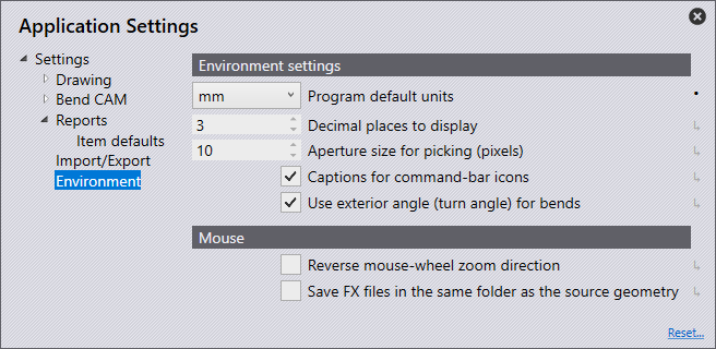
Program default units - The unit can be set to either mm or inches here.

Decimal places to display - Specify how many digits to display after the decimal point (value will be rounded off to two digits).

Aperture size for picking (pixels) - This adjustment specifies how close to an object you must click to select it. If 10 pixels are selected, an object must be clicked within an area of 10 pixels.

Captions for command-bar icons - Select this check box to display explanatory text below the command bar.

captions
Figure 1. Example

Use exterior angle (turn angle) for bends - Select this checkbox to decide whether calculation should be done with the opening angle or the bending angle (exterior angle).

Exterior angle settings is used for Panel Bender.
View Import/Export

      Copyright © 2023 by Metamation. All rights reserved.

    Compiled by Bento