Flux Reference Manual

  • Welcome to Flux
  • Introduction
    • Installing the Software
    • The User Interface
    • Part Workflow
    • The Machine Database
  • Cut
    • Basic Workflows
      • Part Workflow
        • Load Part
        • Sketch Mode
        • Measure
        • Modifying Laser Part
        • Nesting
        • Sequence Navigator
        • NC Code Generation
      • Job workflow
        • Create Job
        • Set Laser Technology Table (LTT)
        • Nesting
        • Automatic Part Placement
        • Manual Part Placement
    • Advanced Topics
      • Geometry Import Options
      • Advanced Tooling Options
        • Editing Microjoints
        • TwinLine
        • FlyLine
        • Dimple Approach
        • Remainder Sheets
        • Pie-Slug Circular Holes
        • Avoid Retooling Pierces
        • Finishing Rules
        • Clone LTT
      • Advanced Nesting Features
        • Mirrored Parts
        • Find a Part in Nest Layout
        • Filler parts in Nest Layout
      • Advanced Tooling Optimization
        • Contour Quality
        • Optimizing Stability with Scrap Cutting
        • Optimizing Tilting Behaviour
        • Space Out Slice Cuts to Avoid Collision
        • Minimize Number of Different Layouts
        • Dynamic Level Setting
      • Advanced Menu Options
        • Context Sensitive Menus
        • Hierarchy of Settings
        • Multi-Selections
        • CSV Output
      • Manual Sheet Slicing Cuts
      • Text on Parts
    • Application Settings
      • Cut CAM
        • Layout
          • Nest Settings
          • Sheet
          • Sheet Handling
          • Skeleton Cuts
          • Work Support
        • Laser CAM
          • Sequence
      • Cut Outputs
      • Cut View
  • Bend
    • Basic Steps of Flux Bend
    • Basic Workflow
      • The Main Panel
      • The Workflow Panel
      • Batch processing
      • Modifying the Geometry
      • The Bend Navigator
      • Editing the Bend Solution
        • Editing a Bend
        • Changing the Bending Sequence
        • Editing a Tool Mount
        • Editing a Bend Setup
        • Editing the Back-Gauges
        • Angle Measurement
        • Using a Pre-Bend
        • Editing multiple mounts
        • Adding a Tooling station
      • Recomputing the Bend Solution
      • Generating Bend Outputs
      • Export Bend Report
    • Design of bend parts
      • Min Radius and Flange Length
      • Corner Design
      • Bending Tolerances
      • Selection of Tools
    • Advanced Workflow
      • Preparation of Bend Parts
        • Preparing a 2D drawing
        • Editing a Drawing
        • Add Bending Information as Text to DXF
        • Measuring and changing Outer Dimension
        • Preparing 3D models
        • Preparing an Assembly
        • Component Detection
        • Form Detection
      • Edit Tools
        • Changing Tool Map
        • Change Tool Segmentation
        • Editing Tool-mount Segments
        • Adding a Gap into the Tool
        • Use a Double-V Adapter
        • Tool Priority
        • Creating a Tool
      • Using Bend Deductions
      • Control Visibility
      • Comment Section in Bend Panel
      • Tools/Machine Tonnage Check
    • Settings
      • Application Settings
        • Bend CAM
          • Bend Outputs
          • Bend View
          • Bend Cell
      • Database Settings
        • Materials
        • Machines
        • Bend Tools
        • Bend Deductions
        • Bend grippers
        • Forms/Components
      • Bend Settings
      • Machine Defaults
  • Robotic Bending
    • Overview of Robotic Bending
    • Basic Steps of Robotic Bending
    • Workflow
      • Part Pickup
        • Pickup from a Pallet
        • Pickup from a Dispenser
      • Insertion Strategy
      • Bending Strategy
      • Regripping (RG) Stations
        • Re-Grip Stations
        • Methods of Regripping
        • Adding ReGrip
        • Modify ReGrip Position
        • Remove ReGripping
        • Regrip with a Jaw Gripper
        • Gripper Panel & Suction Panel
      • Extraction Strategy
      • Part Deposit
        • Adapt Part Deposit
        • Adding Parts & Stacks
          • Deposit Panel
          • Add Separator Sheets
          • Lock Part-Rest
          • Repeat Grid Field
          • Deposit Sequence
        • Deposit Pattern Types
      • Waypoints
        • Adapt WayPoints
        • Display Waypoints
        • Simulate Waypoints
        • Modify WayPoints
        • Properties of Waypoints
    • Advanced Topics
      • Cell Configuration
        • Track Setup
        • Gripper Inventory
        • BendCell settings
      • Gripper Configuration
        • Create/ Edit a Gripper
        • Import Gripper from DXF
    • Troubleshooting Bend Errors
      • Part Pickup Error
      • Collisions with Machine
      • Overtravel of Axis
      • Modifications of Waypoints
      • Collisions while Insertion and Extraction
  • Fold
    • Switching to Fold CAM
    • The Fold View
    • Editing Operations
      • Editing a Bend-Op
      • Editing a Side/Section
      • Changing the Sequence
      • Editing the Blank-holders
      • Editing the Gauging
      • Editing the Blades
      • Editing the Loading
      • Editing the Unloading
    • Tool Management
    • Fold CAM Summary
  • Generic Application Settings
    • Drawing
      • Layers
      • Dimensions
      • View
    • Environment
    • Import/Export
  • Flux Reports
    • Report Designer
    • Fields, Pictures and Tables
    • Bands (sub-reports)
    • Labels, Bitmaps and Shapes
  • Appendix
    • Supported 3D Formats
    • Separator Sheet DXF
Robotic Bending
/
Advanced Topics
/
Gripper Configuration
/
Create/ Edit a Gripper

Create/ Edit a Gripper

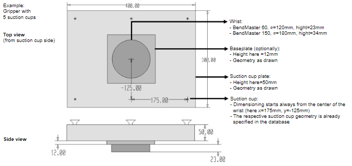
To create an individual gripper, data of the wrist, the optional base plate, the suction plate, and the suction cups, with the corresponding positions are required.

For this purpose a DXF file, including the respective geometry and parameters can be created.

Create your own gripper geometry with the desired suction cups, using the drawing module. Alternatively, an existing DXF drawing can also be imported and edited.

Procedure:

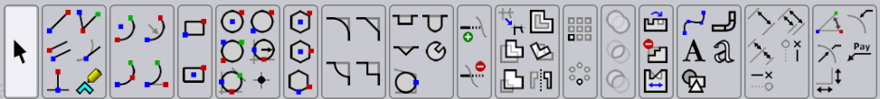
  1. Open a new drawing inside Flux and select the sketch option.

sketch
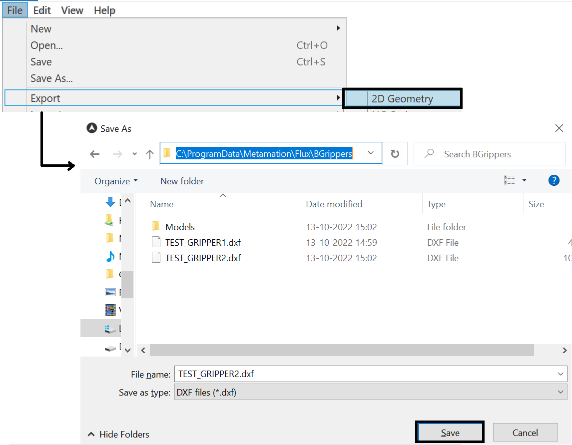
  1. Create a drawing of the gripper with the wrist, base plate and suction cup plate and enter (alternatively, open an existing DXF drawing and adapt it as required). C:\ProgramData\Metamation\Flux\BGrippers\

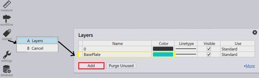
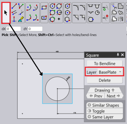
  2. Apply a different colour (e.g. cyan) to the contour of the base plate.

selectlayer
  1. For a correct graphical display of the optional base plate, it must be stored in a separate layer. In the drawing module with the entry BasePlate at the corresponding colour (here cyan), the necessary layer can be define.

applycolor
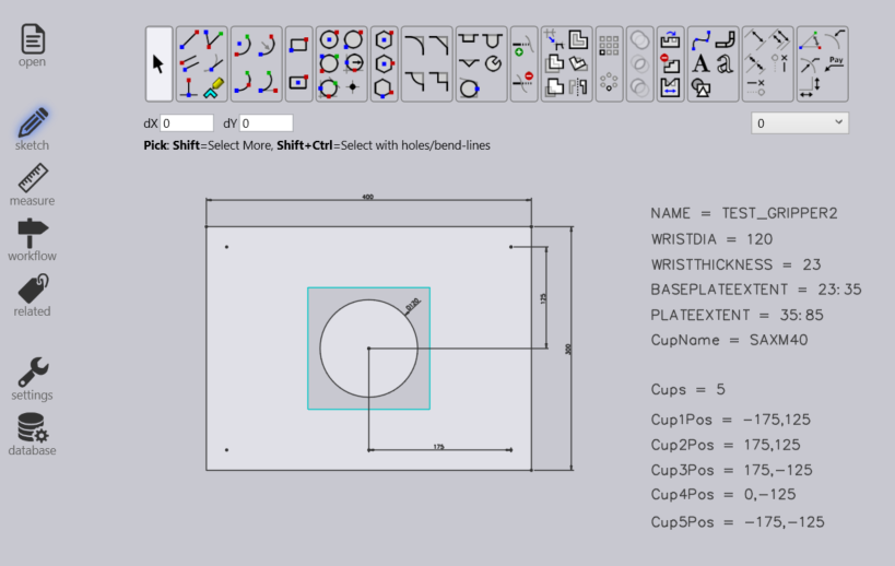
  1. Make sure that the centre of the wrist is at the drawing zero point and input the required text inputs for the parameters.

sketchcenter
  1. Many of the settings for this gripper come from text entities that are of the form KEY=VALUE. Here are the possible keys, with their meanings

key Meaning

Name

The name of the gripper

Weight

Weight of the gripper, in kg.

WRISTDIA

Wrist diameter (must be 120/180 corresponding to BM60/BM150)

WRISTTHICKNESS

The thickness in Z of the wrist cylinder underneath. The wrist cylinder extends from Z=0 to this value

PLATEEXTENT

The Z extent (in the form ZMIN:ZMAX) of the plate. Typically, one sets ZMIN the same as WRISTTHICKNESS, so the plate starts where the wrist-cylinder ends.

BASEPLATEEXTENT

The Z extent of the baseplate (see the section below on Two-Layered-Grippers)

CUPNAME

The type of suction cup used for this gripper (like SAXM50)

CUPS

The number of suction cups

CUP1POS

The position of the first suction cup in the form X,Y

CUP2POS

The position of the second suction cup

CUPNPOS

The position of the Nth suction cup

CUPDIA

Can be used instead of CUPNAME to specify a suction cup (not recommended).

Key

Meaning

  1. Export as DXF file under the below mentioned path after updating the text parameters from the drawing module.
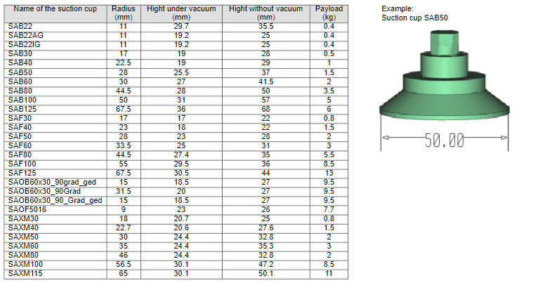
exportgripperdxf

Suction Cup Types

In the Bend database there are different types of suction cups available, which can be used when configuring a new gripper.

newitem38
Figure 1. Suction cup database
newitem42
Figure 2. Example gripper from database

Contents

  • Suction Cup Types
Gripper Configuration Import Gripper from DXF

      Copyright © 2023 by Metamation. All rights reserved.

    Compiled by Bento