Cut Technologies
Setting the Laser Technology Table (LTT)
For a given material, there are usually multiple LTTs that can be used. Flux can sort the LTTs and select a default LTT based on various criteria.
-
The LTTs will be listed with the most frequently used ones at the top, and further highlighted by a star whose size is based on the frequency of usage. The bigger the star, the more frequent is its usage.
-
LTTs are also sorted based on the previously used measuring unit (mm or inch).
-
Further, LTTs are then sorted based on gas type, with N2 being the highest priority (followed by O2, Air and Argon).
-
Finally, they are sorted based on whether the LTT is from standard table or from an additional table.
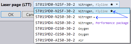
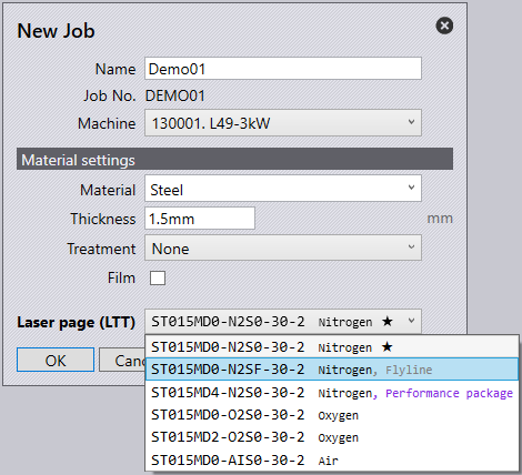
Flyline
Flyline is used for high-speed processing with reduced quality expectations.
-
Click on the New Job icon.
-
Select a Flyline from the Laser page (LTT) drop down menu.
Automatic detection
After a part has been imported and tooled up, you will see that flyline grids within a part will automatically be detected and tooled using flyline. It is not necessary that the grids are regular for the software to identify and tool up with flyline, they can be partial or staggered.
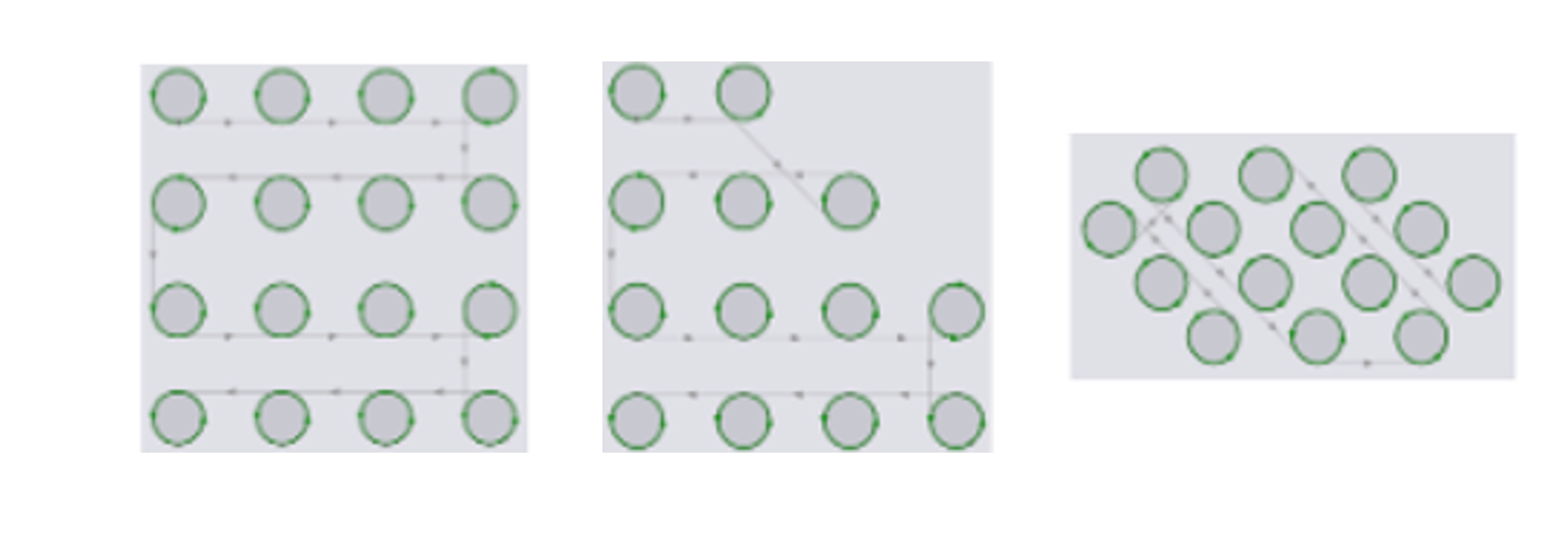
These grids can be at any angle.
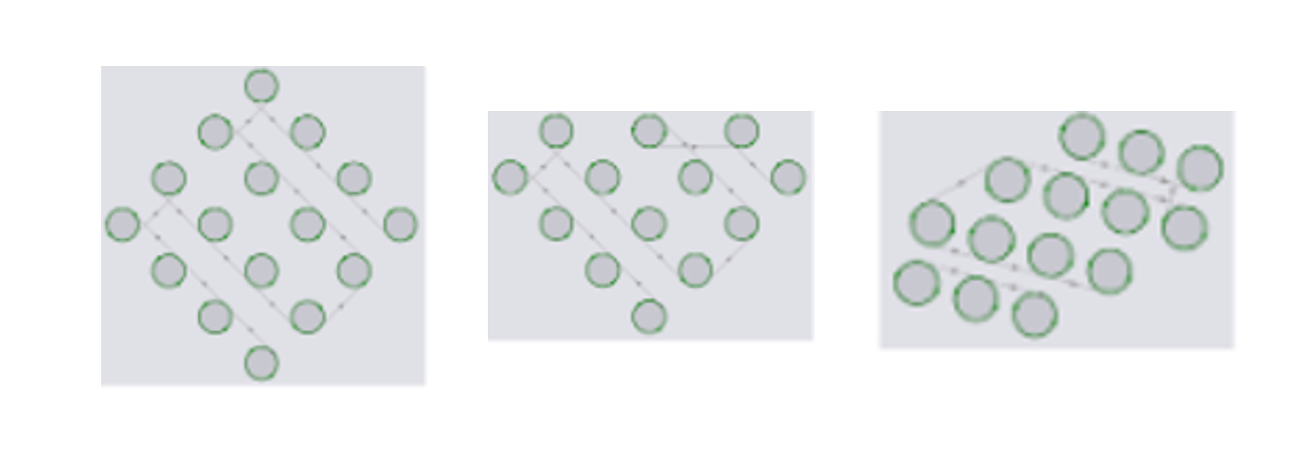
When cutting the circles, the software will cut all the circles in the same direction, clockwise or anti-clockwise depending on the setting that controls the cutting direction for inner contours in the LTT. All transitions when cutting an obround grid are smooth. Where necessary, the software will introduce two curves (5mm diameter) to ensure that the head moves out from a cut tangentially and moves into the next cut tangentially.
Finishing Rules
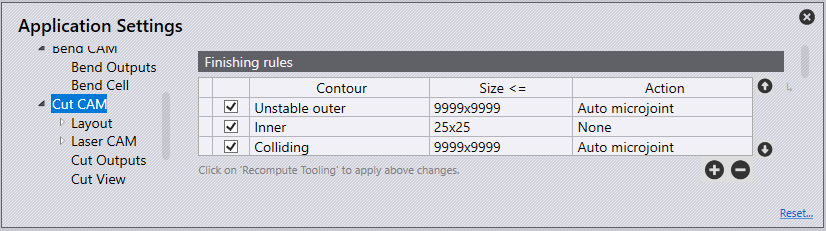
Finishing rules define all processes done automatically after nesting and have many benefits including collision prevention, restoration to balance potential tilting of parts and making optimal use of an entire worksheet surface.
When auto-tooling, the order of rules in this list is important. When FluxCut® generates tooling for a contour, it checks this contour against each rule in the list, starting from first rule. If the shape matches any rule, the corresponding action is applied; the software does not process any further rules for this contour. The checkbox at the beginning of each row can be used to temporarily disable any rule without having to delete it.
| These finishing rules are applied at the time of auto tooling a part. Hence, any change done here will take effect only when you recompute tooling. These settings have no effect whatsoever at the layout level. |
-
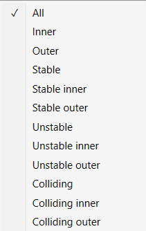
Contours are selected based on the below filters:
-
All - Contours are not filtered based on contour type if ‘All’ is the selected option for contour type.
-
Inner – All inner contours of a part are eligible for applying this rule.
-
Outer – All outer contours of a part are eligible for applying this rule.
-
Stable – All contours (inner as well as outer) which will remain stable on slats are eligible.
-
Stable Inner – All inner contours will remain stable on slats.
-
Stable Outer – All outer contours will remain stable on slats.
-
Unstable – All contours (inner as well as outer) which will either tip or fall through the slats are eligible.
-
Unstable Inner – All inner contours that are unstable on slats.
-
Unstable Outer – All outer contours that are unstable on slats.
-
Colliding - All unstable contours that are too close to the other contours of the part. If this contour were cut first, an adjacent contour cannot be cut without the risk of head collision with tipping contour.
-
Contours that are stable on slats are never considered to be colliding.
-
If an inner contour is too close to another inner contour, both unstable, then both will be marked as colliding.
-
If an inner contour is too close to an outer contour, only the inner contour will be marked as colliding. It is unnecessary to mark the outer contour as colliding as it will almost always be cut after the inner contour.
-
The new parameter Allowance when routing around tipping holes is used to decide if two contours are too close.
-
-
Colliding Inner - All inner contours that are colliding.
-
Colliding Outer - All outer contours that are colliding.
-
-
Size - The maximum limiting size of contours for which this rule applies. You can either type in the size in the form of "width x height" or type in just one number if both width and height have the same value.
-
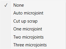
Action - The type of action to perform; auto micro-joint, cut up scrap and so on.
-
None – No special action is taken.
-
Auto Microjoint – Applies micro-joint(s) on the contour. The software will automatically decide how many micro-joints are required based on the parameter Maximum allowed dip into slats.
-
Cut up scrap – Cut larger cut outs.
-
One micro-joint – Create exactly one micro-joint on the contour.
-
Two micro-joints – Create exactly two micro-joints on the contour.
-
Three micro-joints – Create exactly three micro-joints on the contour.
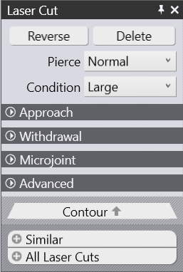
Microjoint
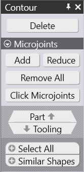
After a part has been tooled, modification of the tooling can be done by the user. Selecting an element of the laser tooling will display the Laser Cut panel, from this select contour which will open the Contour panel.
-
Delete - This will remove the tooling for the selected contour.
-
Add - This option will add or increase microjoints on the contour. Click this option to add a microjoint automatically on the contour.
-
Reduce - This option will remove a microjoint. Repositions remaining microjoints to be at equal distances.
-
Remove All - This option will delete all microjoints.
-
Microjoints - This is a special mode where the user can interactively add/remove microjoints by clicking on the contour. Usual snap points are available to insert microjoints. A special snap point at a standard offset from the corner (entered in the ‘Corner Offset’ field shown below) is also available.
-
Part - This is a navigational option which will navigate to the part level options
-
Tooling - This is a navigational option which will navigate you again to Laser Cut panel.
-
Select All - This will select all contours in the part, allowing microjoints to be added/removed.
-
Similar Shapes - This option will select all identical laser cuts in the part. For example, laser tooling of all 10mm size circles can be selected.
Microjoint Settings
-
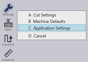
Click on the settings icon and select Application settings.
-
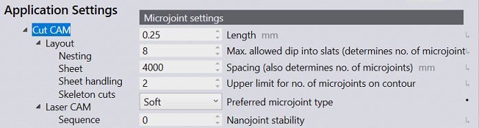
Select Cut CAM to edit Microjoint settings.
-
Length – Enter the size of the microjoint.
-
Max. allowed dip into slats (determines no. of microjoints) – This is the maximum distance the microjoint is allowed to dip into slats on a contour.
-
Spacing (also determines no. of microjoints) – This setting along with the above setting, determines number of microjoints. Of the two methods, one with the higher microjoint count will be used.
-
Upper limit for no. of microjoints on contour – The maximum number of microjoints allowed on the upper-most side of the contour.
-
Preferred microjoint type:
-
Hard – Hard coded microjoint that cannot be modified on the machine.
-
Soft – Microjoint that can be modified on the machine.
-
Nano – An alternative to usual microjoint, where no approach is required. Possible only on large contours. Commonly used in twinline processing.
-
-
Nanojoints stability – Controls the stability for nanojoints.