Part Deposit
After the bending is completed, the finished part is deposited on a pallet or conveyor, or dropped into a basket. Various settings are used to control this deposit operation:
-
The position, type and orientation of the deposit pallet.
-
The grid of parts on the pallet (rows, columns, layers).
-
The orientation of the part on the pallet.
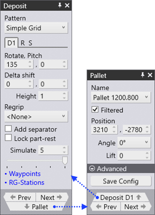
These settings are controlled mainly from the Deposit panel, and also from the Pallet panel that is supporting the deposit. Here is how these panel are accessed:
-
Click on the deposit pallet (or conveyor, or basket) to open the Pallet panel and navigate to the deposit D1.
-
Click twice on the cells like D1, D2 etc on the bend navigator to open the Deposit panel.
-
Click on one of the finished parts lying on the deposit pallet to open the Deposit panel.
In addition, these two panels have navigation links ( ) leading to each other.
Pallet Panel
The Pallet panel is used to select a deposit pallet and position it in the cell. You can open this panel by clicking on a pallet, and Flux will position the simulation timeline so the robot is poised above the pallet (to make it easier to validate the pallet position and orientation).
This panel is discussed in more detail in the section on Part Pickup. In brief, you can select different types of pallets, move them and re-orient them.
As you move or rotate the pallet, the stack of deposit parts on it also follows suit (along with the robot). Thus, you can quickly determine if the locations are all reachable during deposit.
Deposit Panel
The Deposit panel controls most of the settings for the Deposit. The settings available here depend on the pattern that is being used. You can switch between some of these patterns, though not all Patterns are suitable for all parts. For example, the Drop to Basket pattern is usable only if you are using the mechanical gripper with a small part.
Deposit tab D1 (and optionally D2)
There are several deposit Patterns available (Simple, Alternating, Weave, Basket etc). Some of these patterns (Alternating, Weave) use parts deposited in two different orientations. The orientation and other settings for these parts are edited in the D1 and optionally the D2 tabs (these also correspond directly with the D1 and D2 deposits on the main navigation bar on the top).
-
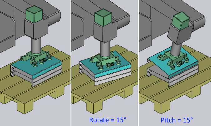
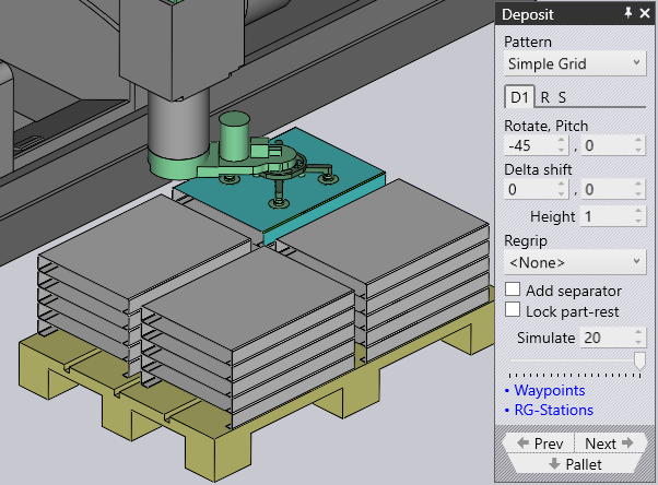
The Rotate and Pitch settings control the orientation of the part at the point of drop. The Rotate setting (also known as yaw) turns the part around the wrist local vector, while the Pitch axis rotates the part about the machine Z axis.
-
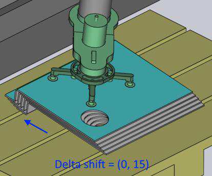
The Delta Shift vector is used to shift each successive part in the deposit relative to the part underneath. You can see a shift of +15mm in the X direction below, used to stack the parts tightly against each other in a stable manner:
-
The Height parameter controls the height above the stack from which the part is released (the part falls by this distance when coming to rest on the stack).
-
Click on the Regrip drop down menu and select <Add> to add a new regrip (R1) before the deposit – this allows you to deposit the part upside down, or with a different gripper orientation that was used for the last bend. You can also choose any other existing regrip added earlier which will be listed in the drop-down. Selecting <None> will remove the regrip used.
-
The Add separator setting is used to place a separator sheet after each layer of the deposit so the next set of parts can be deposited on a flat surface again.
-
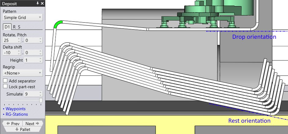
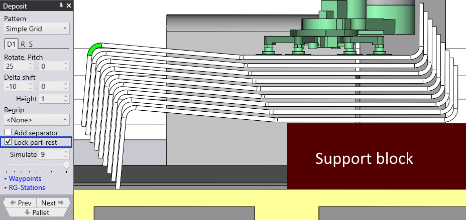
Lock part-rest setting is used to lock the rest-orientation of the part to the drop-orientation.
-
This feature is useful when the part needs to be rested on a supporting block.
-
Select the lock part-rest check box and adjust the delta shift vector in 'Z' direction to get a perfect stack.
Repeat tab (R)
The D1 and D2 tabs shown above are used to specify the orientation of the first part of the deposit. Then, the settings in the Repeat tab are used to replicate that into a grid of rows (Z), columns (X) and layers (R). The image alongside shows a deposit with many of these settings changed from defaults.

-
The Grid settings are used to set up the number of columns and rows in the deposit.
-
The Layers setting specifies how many parts are stacked on top of each other in each pile.
-
The Gap settings are used to specify the gap between successive columns or successive rows. If you set this to 0, the rows or columns are exactly touching each other.
-
The Stack shift settings are used to displace the complete stack of all the parts away from the center of the pallet.
Sequence tab (S)
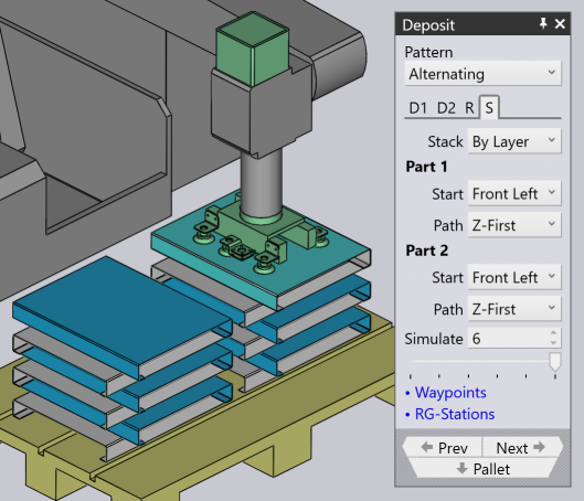
The Sequence tab is used to control the sequence in which the parts are deposited. The settings on this sequence tab are shown alongside. In this example, there are two deposit orientations D1 and D2, and there are correspondingly two sets of sequence settings (this means you can start D1 layers from one corner, while D2 layers may start from a different corner).
-
The Stack setting has two options: By Layer or By Pile. In this example here, stacking By Layer would build up both the adjacent piles in unison – this means that successive deposits would happen in pile 1, pile 2, pile 1, pile 2 etc. Thus both the piles will rise in height together. When you stack By Pile, all the parts of the pile on the left are deposited first before we start placing any parts on the right pile.
-
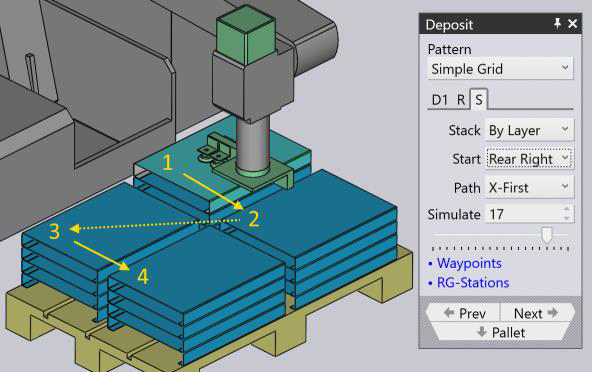
The Start corner and Path settings are used when there are multiple rows or columns, and decide which corner the stacking starts from, and whether the stacking then proceeds row-by-row, or column-by-column. This can be useful especially with an off-center gripper, since a different starting corner may cause a collision between the gripper and the previous part that was already deposited.
-
The image shows an example where we start from the Rear Right corner and proceed to deposit X-First (the numbers 1, 2, 3, 4 shows the sequence of deposits within this layer). If we started this deposit from the bottom Front Left corner (the default), we will have the situation that when we are depositing the second part in the layer, the gripper will collide with the previous part (because it extends off-center out of the part bounds).
-
The Simulate settings (both the number spinner and the slider) can be used to scrub through the deposits to see the order in which they happen on the pallet. This is especially useful when adjusting the start corner and the path settings. In the image above, we are seeing the deposit of part 17 (of 20). If we move the slider right (or adjust the value in the Simulate input box), you can view the gripper in position for deposits 18, 19 and 20.
Patterns
Simple Grid
The Simple Grid pattern is the most commonly used, and just stacks parts in a rectangular grid on the pallet.
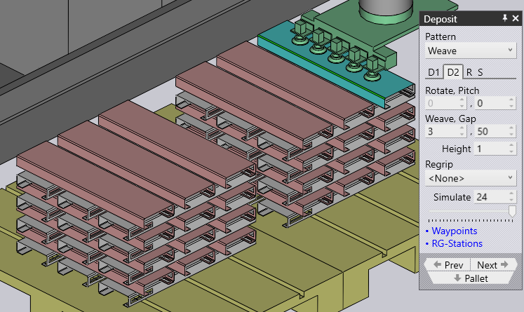
Weave
The Weave pattern is useful with long and thin parts. The parts in the D2 layers are placed 90° from the parts in the D1 layer as shown alongside.
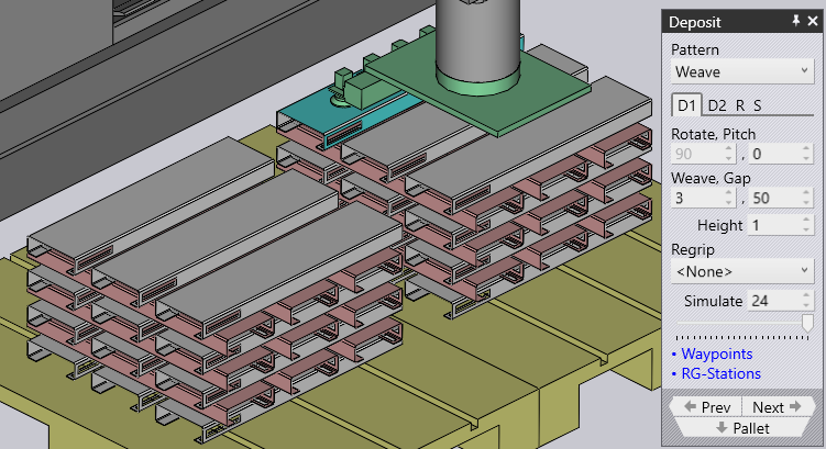
-
The Weave setting controls the number of parts stacked side by side in each layer of the weave.
-
The Gap is the gap between each of these parts within the weave
-
The Grid settings on the Repeat tab can then be used to repeat the entire weave stack multiple times on the pallet. In this example, the weave stack is repeated twice (2 columns, 1 row).
-
The Gap setting on the Repeat tab is used when the weave is repeated and specifies the pitch between the weave layers.
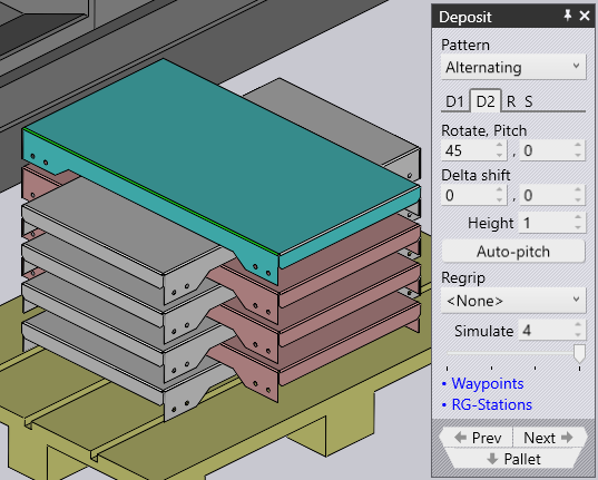
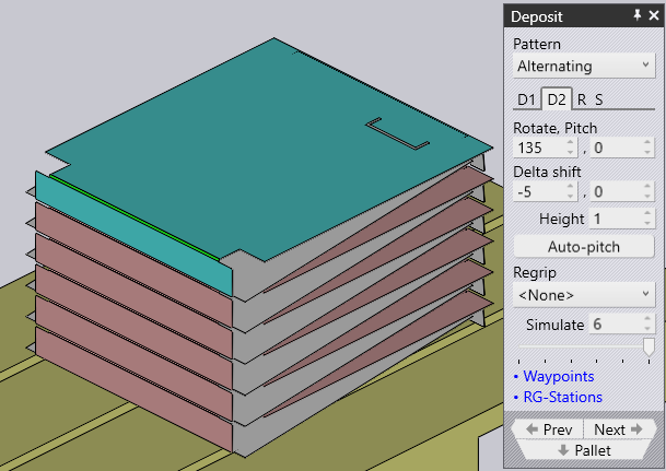
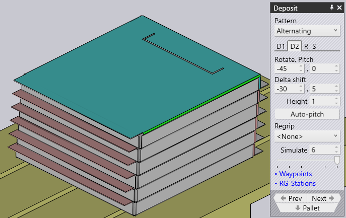
Alternating
The Alternating pattern is the most flexible. In this pattern, you can control the orientation, flip and relative shift of every alternating layer.
Alternate pattern provides a more stable and also a compact stacking of parts.
| Adjust the Delta shift values in D1, D2 and use the Regrip before to lock the parts with each other. |
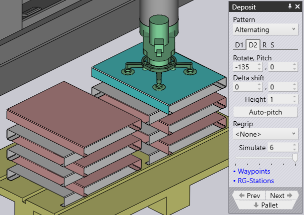
Examples of Alternate Stacking:
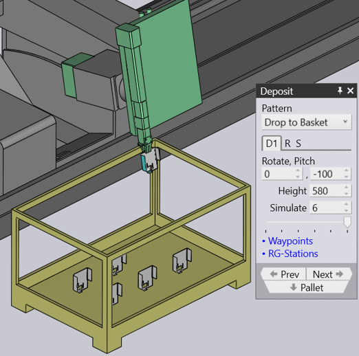
Drop to Basket
This pattern is used to drop small parts into a collection basket, using the mechanical gripper.
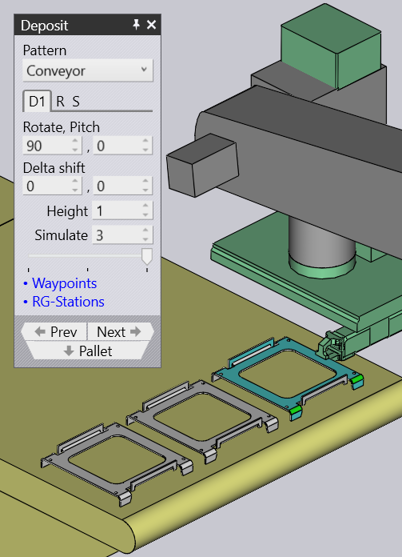
Conveyor
Conveyor pattern is used to deposit parts on a part conveyor. This option is essential when long thin parts are deposited on conveyor.
| When mechanical jaw gripper is used for medium size parts, all other pattern types will be disabled for selection, except for conveyor pattern. |
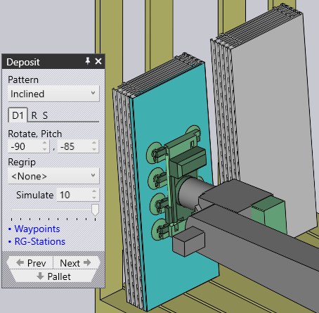
Inclined
The Inclined pattern is used to stack parts vertically against a wall (or a pallet that has a side-wall).
| This pattern is not always available. The part must be large enough for this to be feasible. For small parts, the robot cannot reach down low enough to stack the part against the wall. |
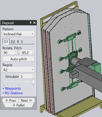
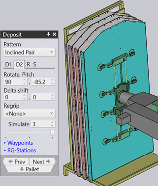
Inclined pair
This pattern type is very similar to alternating pattern, except the parts are deposited vertically as a pair.
An additonal Regrip is introduced either in D1 or D2 deposit to make a pair.
Auto-pitch determines the lean angle of the stack automatically.
Pitch setting is used to adjust the lean angle of the stacking and Delta shift values are used to move in the part in X and R axes to make a more compact stack.
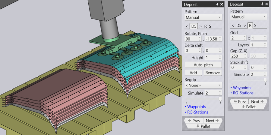
Manual
The Manual pattern is used to place each layer of parts at a slightly different orientation.
-
Use the Add button to add a new part on top of the upper-most layer.
-
Use the navigation buttons next to the Dn tab to go to the previous or next layer.
-
The Delta shift, Rotate and Pitch settings can be used to adjust the part so it sits better on the part below. You can also use the Delta shift and click on Auto-pitch to ask Flux to compute an optimal pitch angle.
-
Use the Remove button to remove the topmost part.
-
After a manual stack is created, you can use the settings on the Repeat tab (R) to repeat the same stack across the pallet. The image above shows the same stack repeated for 2 columns, 1 row with a gap of 250 mm between columns.
-
The settings on the Sequence tab (S) can be used to control whether the parts are stacked by layer or by pile. If you use the pile-by-pile stacking, all the parts on the first pile are finished before we start on the second pile.