Robotic Bending
A robotic bending process is programmed as three phases: insertion, bending and extraction. Flux will use several different strategies to control the robot trajectory during these phases, but you can also interactively edit these choices using the Robot Path panel. You can reach the Robot Path panel in one of these ways:
-
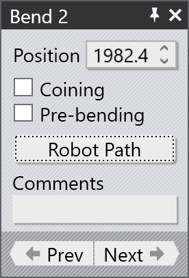
Click twice on a bend number in the navigator grid on the top to open the Bend panel for that bend. Then, click on the Robot Path button there to get to the Robot Path panel. You can see this button highlighted in the image on the right.
-
With any bend operation active, just click on the gripper or the wrist of the robot to open the Robot Path panel.
Once the Robot Path panel is open, you can then click the Prev or Next navigation buttons there to edit the robot path for the other bends in the part. Also, with this panel open, you can just click on one of the bend numbers in the bend navigator at the top of the window, and you are then editing the robot path for that bend.
Insertion
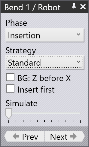
To edit the part insertion phase of the cycle, select Insertion from the Phase selector. The Robot Path panel will then look like the image alongside:
-
The Strategy is used to select between different insertion strategies. In particular, the From Left or From Right strategies can be used to insert the part from the left or the right of the punch (sliding the part in between the punch and die). This can be useful if the part has some contour that might interfere with the punch as the ram is closing.
-
The BG: Z before X strategy is used to control how the back-gauge moves from the previous bending operation to this one. It is useful in the cases where the gauging position for this bend is closer to the die than the previous bend. If this is turned on, the back-gauges move first in the Z direction to get to the target Z1 and Z2 positions, and then move forward in X to the engagement position. This reduces the possibility of collisions with the part during the gauge movement.[1] (The simulation updates when you change this setting, so you can visually see the gauge movement path).
-
Normally, the back-gauge moves from the previous bend’s position to the gauging position required for this bend as soon as the previous bend is completed and the part is extracted out. With the Insert first strategy, this movement is delayed. The part is first inserted and rested on the die. Then, the gauges are moved into position. This can be useful in situations where there are some downward facing flanges in the part that might collide with the gauges if they were already in position during the part-insertion. (This simulation is updated when you change this setting, so you can see the gauge movement delayed until after part insertion is complete).
-
The Simulate slider can be used to quickly simulate just the insertion phases of this bend so you can quickly review the changes you are making.
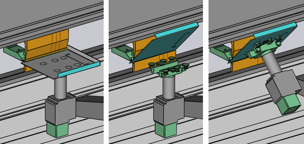
Bending
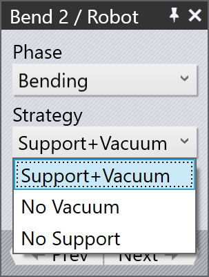
To edit the bending phase of the cycle, select Bending from the Phase selector. The Robot Path panel then looks like the image alongside.
-
Support+Vacuum is the default strategy, suitable for most bends. With this strategy, the gripper holds the part with suction on, and supports it as the bending takes place.
-
With the No Vacuum strategy, the vacuum is turned off as the bending begins. The gripper still moves with the part, support it as the bending progresses.
-
With the No Support strategy, the bending happens without any support from the gripper. The vacuum is turned off and the part is bent with the gripper remaining in the original (flat) position. After the bend is complete, the gripper moves up and picks up the part again.[2]
There is no visual difference in the simulation when the No Vacuum strategy is used (only the generated NC code is different). But when the No Support strategy is used, you can see the gripper releases the part and waits for the bend to be complete before picking it up again.