Cut View
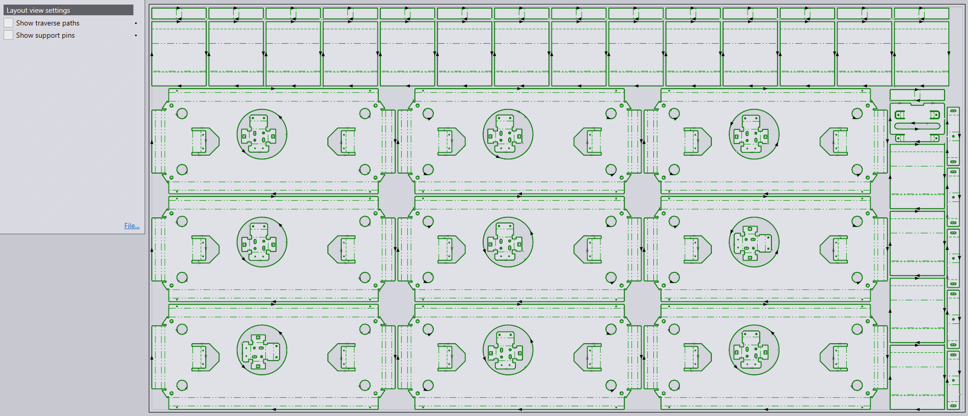
Layout View Settings
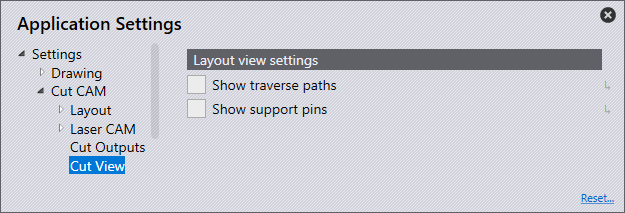
Show traverse paths: Rendering all traverse lines is almost instant. User actions like moving parts on the layout or changing some settings that affect sequencing/routing would mean that sequence & routing have to be recomputed when necessary.
Select Show traverse paths to see black dotted lines in the layout.
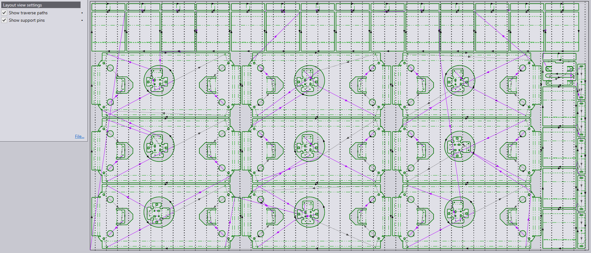
| In general, when the user is engaged in actions of modifying the layout (moving and adding parts to the layout), he or she must turn OFF the Show traverse paths option. |
Show support pins: For minimizing tilting and welding parts on the slats. With the sequence tab open, when the user selects any tooling item, the software will paint red dots inside that contour indicating the points which are supported by pins. Inner pins are not shown as they are not significant for tipping calculations and will simply end up cluttering the scene.
Select Show support pins to see traverse path lines with arrow heads in the layout.