TecZone Laser Reference Manual

  • Welcome to TecZone Laser
  • Introduction
    • Installing TecZone
    • TecZone Laser User Interface
    • Workflow Panel
    • Machine Database
  • Basic Workflows
    • Part Workflow
      • Load Part
      • Sketch Mode
      • Measure
      • Modifying Laser Part
      • Nesting
      • Sequence Navigator
      • NC Code Generation
    • Job workflow
      • Create Job
      • Set Laser Technology Table (LTT)
      • Nesting
      • Automatic Part Placement
      • Manual Part Placement
  • Advanced Topics
    • Geometry import options
    • Advanced Tooling Options
      • Editing Microjoints
      • TwinLine
      • FlyLine
      • Dimple Approach
      • Remainder Sheets
      • Skeleton Cuts
      • Pie-slug Circular Holes
      • Avoid Retooling Pierces
      • Finishing Rules
      • Clone LTT
    • Advanced Nesting Features
      • Mirrored Parts
      • Find a Part in Nest Layout
      • Filler parts in Nest Layout
    • Advanced Tooling Optimization
      • Contour Quality
      • Process Stability
      • Optimizing Stability with Scrap Cutting
      • Optimizing Tilting Behaviour
      • Space Out Slice Cuts to Avoid Collision
      • Minimize Number of Different Layouts
      • Dynamic Level Setting
    • Advanced Menu Options
      • Context Sensitive Menus
      • Hierarchy of Settings
      • Mult-Selections
      • CSV Output
    • Hand Drawn Sheet Slicing Cuts
    • Text on Parts
    • Generate Customized Reports
  • Application Settings
    • Drawing
      • Layers
      • Dimensions
      • View
    • Cut CAM
      • Layout
        • Nest Settings
        • Sheet
        • Sheet Handling
        • Skeleton Cuts
        • Work Support
      • Laser CAM
        • Cut Outputs
        • Cut View
    • Reports
      • Item Defaults
    • Import/Export
    • Environment
  • Impressum
Advanced Topics
/
Geometry import options

Geometry import options

When you import a part via dxf you could determine the processing method by using different layers. One main application is to distinguish lines which are cut (e.g. Layer 0) from lines which are only marked (e.g. Layer _MARK)

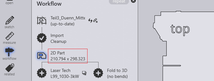
To check the layers you have to switch to the ‘2D part’ mode in the workflow manager

Report

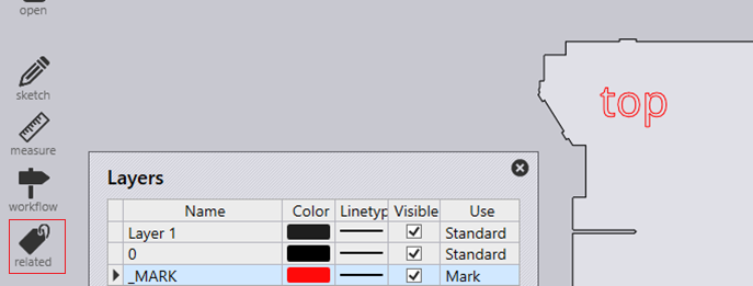
You could give layers specific colors with the layer function in the menue ‘related’.

Report

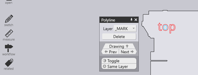
If you click a poly line you will see on which layer a certain contour is

Report

After the technology is calculated you see that the laser processing was set to condition ‘mark’

Report

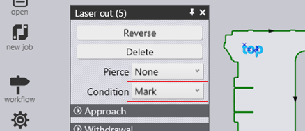
See also the setting details:

Layers

Layer Mapping

Advanced Topics Advanced Tooling Options

      Copyright © 2024 TRUMPF Werkzeugmaschinen SE + Co. KG. All rights reserved.

    Compiled by Bento